Inter stage seal housing having a replaceable wear strip

a technology of inter-stage seal and wear strip, which is applied in the field of turbine engine wear strip replacement in the inter-stage seal housing, can solve the problems of increasing service expenses, affecting the cooling efficiency of the associated rotor disc cavity, and affecting the overall engine efficiency and performance of the turbine engine, so as to prevent unwanted relative movement and wear, and minimize the disassembly effect of fasteners

Active Publication Date: 2012-02-23
MITSUBISHI HITACHI POWER SYST AMERICAS
View PDF9 Cites 7 Cited by
  • Summary
  • Abstract
  • Description
  • Claims
  • Application Information

AI Technical Summary

Benefits of technology

[0006]In accordance with another aspect of the present invention, the upstream sealing surface of the secured segment strip forms an upstream contact sealing surface with the seal housing, the downstream sealing surface of the secured segment strip forms a downstream contact sealing surface with a stationary member of the turbine engine, the right circumferential sealing surface of the secured segment strip forms a first circumferential contact sealing surface with another left circumferential sealing surface of an adjacently secured sealing segment, and the left circumferential sealing surface of the secured segment strip forms a second circumferential contact sealing surface with another right circumferential sealing surface of another adjacently secured sealing segment, wherein the first and second circumferential contact sealing surfaces are configured to prevent leakage between adjacently secured segment strips with the first and second circumferential contact sealing surface having a step portion.
[0007]According to another aspect of the present invention, the plurality of fasteners comprises a first fastener fo...

Problems solved by technology

However, engine operation eventually causes the downstream contact sealing surface 13 of the inter stage seal housing 10 to wear with the amount of wear being proportional to the number of hours of engine operation.
Excessive wear of the downstream contact sealing surface 13 can create a leak path, which can negatively affect the cooling efficiency of the associated r...

Method used


Image

  • Inter stage seal housing having a replaceable wear strip
  • Inter stage seal housing having a replaceable wear strip
  • Inter stage seal housing having a replaceable wear strip

Examples


first embodiment

[0024]In the following, a first embodiment of the present invention is described with reference to FIGS. 3-8.

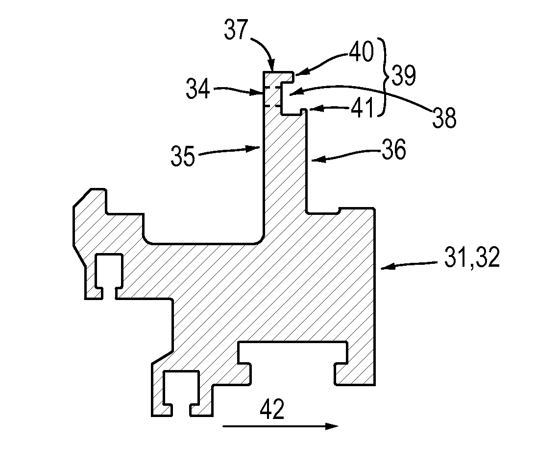
[0025]FIG. 3 is an elevational view of a sealing assembly 20 that includes an inter stage seal housing 30 which prevents the flow 42 from passing between the seal housing 30 and another non-rotating component of a turbine, such as the turbine stator (not shown) or stationary vane component (not shown) in accordance with the first exemplary embodiment of the invention. Note that the seal housing 30 may be used in all types of turbine engines, including gas turbine engines, steam turbine engines, aircraft engines, and others. As shown in FIG. 3, the seal housing 30 may be configured with an upper half inter stage seal housing 31 and a lower half inter stage seal housing 32 having a horizontal split 33 located between the upper and lower half seal housings 31, 32. The upper and lower seal housings 31, 32 each include a plurality of through holes 34.

[0026]FIG. 4 is an enlarged cr...

second embodiment

[0038]Next, a second embodiment of the present invention is described with reference to FIGS. 9-12.

[0039]The second embodiment is different from the aforementioned first embodiment in that the replaceable wear segment strip 50 does not include any threaded holes 51 and the upper and lower seal housings 31, 32 do not include any through holes 34 for aligning the threaded holes 51 of the segment strip 50 when the segment strip 50 is installed in the feature 38. Further, no fastening hardware or fastener retention hardware is used to fasten or secure the segment strips 50 to the seal housings 31, 32. The remaining points are similar to those of the first embodiment so that their descriptions are omitted.

[0040]As a result, in the second embodiment, since the replaceable wear segment strip 50 does not include any threaded holes 51, the specific retention geometry 39 of the feature 38, which includes the radial locating flange 40 and the axial retention flange 41, is the only mechanism us...


PUM


Abstract

An inter stage seal housing for a turbine engine having upper and lower half inter stage seal housings in which a contact sealing surface of the seal housing is restored after an interval of engine operation. The contact sealing surface is restored by fitting a replaceable wear strip on the downstream sealing surface of the seal housing. In order to fit the replaceable wear strip, a circumferential groove is machined along an outer peripheral edge of the seal housing. The groove is machined to include axial location and radial retention such that the wear strips can be slid into the upper half and lower half inter stage seal housing circumferentially from the horizontal joint. The groove includes through holes and the wear strips include corresponding threaded holes such that the wear strips can be fastened in the groove by fasteners and fastener retention hardware.

Description

FIELD OF THE INVENTION[0001]This invention relates to using a replaceable wear strip in an inter stage seal housing for a turbine engine, and more particularly, but not by way of limitation, to using the replaceable wear strip to restore a downstream sealing surface of the inter stage seal housing for the turbine engine after prolonged engine usage.BACKGROUND OF THE INVENTION[0002]An inter stage seal housing is used in a turbine engine to form a seal between itself, a rotating component, and another non-rotating component of the turbine engine, such as the turbine stator or a stationary vane component. FIG. 1 shows an enlarged cross-sectional view of a conventional inter stage seal housing 10, which includes a downstream contact sealing surface 13. FIG. 2 shows an enlarged fragmentary cross-sectional view of the conventional inter stage seal housing 10 shown in FIG. 1 together with a stationary airfoil 14. As shown in FIG. 2, the downstream contact sealing surface 13 of the conventi...

Claims


Application Information

Patent Timeline
IPC IPC(8): F01D11/12
CPCF01D11/001F01D11/122F01D11/12F05D2240/55F05D2250/37F05D2230/72F05D2240/40F01D9/00F01D11/00
Inventor SCIMECA, SANTO F.GARNER, CHAD
Owner MITSUBISHI HITACHI POWER SYST AMERICAS
Why Eureka
Try Eureka