Built-in antenna and method for improving antenna efficiency

a built-in antenna and antenna efficiency technology, which is applied in the direction of elongated active element feed, resonance antenna, waveguide type devices, etc., can solve the problems of reducing antenna radiation efficiency, band also decreasing, and performance-to-size relation cannot be designed in a complementary manner, so as to improve antenna efficiency and wide bandwidth , excellent radiation properties

Active Publication Date: 2012-02-23
SAMSUNG ELECTRONICS CO LTD
View PDF5 Cites 45 Cited by
  • Summary
  • Abstract
  • Description
  • Claims
  • Application Information

AI Technical Summary

Benefits of technology

[0016]Aspects of the present invention are to address at least the above-mentioned problems and / or disadvantages and to provide at least the advantages described below. Accordingly, an aspect of the present invention is to provide a built-in antenna implemented to have a wide bandwidth and an excellent radiation property even if a metal construction exists, and a method and an apparatus for improving antenna efficiency.

Problems solved by technology

These antennas have a disadvantage in that a performance-to-size relation cannot be designed in a complementary manner.
More particularly, when a metal construction and a metal component are located near an antenna, there is a problem in that the antenna's radiation efficiency is decreased and a band is also decreased.
In addition, it is not difficult to design an antenna for the portable electronic device of the related art since an exterior of the portable electronic device is formed with a dielectric material, such as plastic.
However, as the portable electronic device gradually decreases in size and thickness, a space for placing the antenna is being decreased, and a distance to the surrounding metal construction and metal component is being narrowed.
However, it is difficult for the aforementioned built-in antenna of the related art to satisfy such a requirement as a compact size, efficiency increase, and a wide band in such extreme surrounding conditions.
However, if an antenna pattern is deployed far from a metal component and a metal construction, a space for placing the antenna becomes further decreased and thus it becomes difficult to ensure more space.
In addition, a method of performing an insert molding process on an antenna part impairs an outer appearance of the antenna since there is a disparity between metal and insert molding processes in a design aspect even if it is easy to ensure radiation efficiency.
Furthermore, although radiation efficiency may be ensured by using a method of increasing a thickness of the portable electronic device, this method cannot make the portable terminal slim, which is a current design trend.
That is, if there is a metal structure extended from the ground in the front surface of the antenna, a near field induces current in a corresponding metal member and generates thermal loss and radiation loss together with lossy volume, thereby resulting in an overall radiation efficiency deterioration.
However, this method has a problem in that a disparity occurs between metal and insert molding processes in a design aspect.
A method in which the entire front surface of the device is subjected to metal processing and a distance between an antenna and the front-surface metal member is increased to the maximum extent possible by increasing a thickness of the terminal has a problem in that a slimming trend in the designing of the terminal cannot be satisfied.
A method in which a front-surface metal member of a terminal is separated from a main ground can utilize the front-surface metal as a radiator, but may cause an Electro-Static Discharge (ESD) problem or a problem of radiation efficiency deterioration due to user influence.

Method used


Image

  • Built-in antenna and method for improving antenna efficiency
  • Built-in antenna and method for improving antenna efficiency
  • Built-in antenna and method for improving antenna efficiency

Examples


Embodiment Construction

[0047]The following description with reference to the accompanying drawings is provided to assist in a comprehensive understanding of exemplary embodiments of the invention as defined by the claims and their equivalents. It includes various specific details to assist in that understanding but these are to be regarded as merely exemplary. Accordingly, those of ordinary skill in the art will recognize that various changes and modifications of the embodiments described herein can be made without departing from the scope and spirit of the invention. In addition, descriptions of well-known functions and constructions may be omitted for clarity and conciseness.

[0048]The terms and words used in the following description and claims are not limited to the bibliographical meanings, but, are merely used by the inventor to enable a clear and consistent understanding of the invention. Accordingly, it should be apparent to those skilled in the art that the following description of exemplary embod...


PUM

PropertyMeasurementUnit
specific lengthaaaaaaaaaa
specific distanceaaaaaaaaaa
lengthsaaaaaaaaaa

Abstract

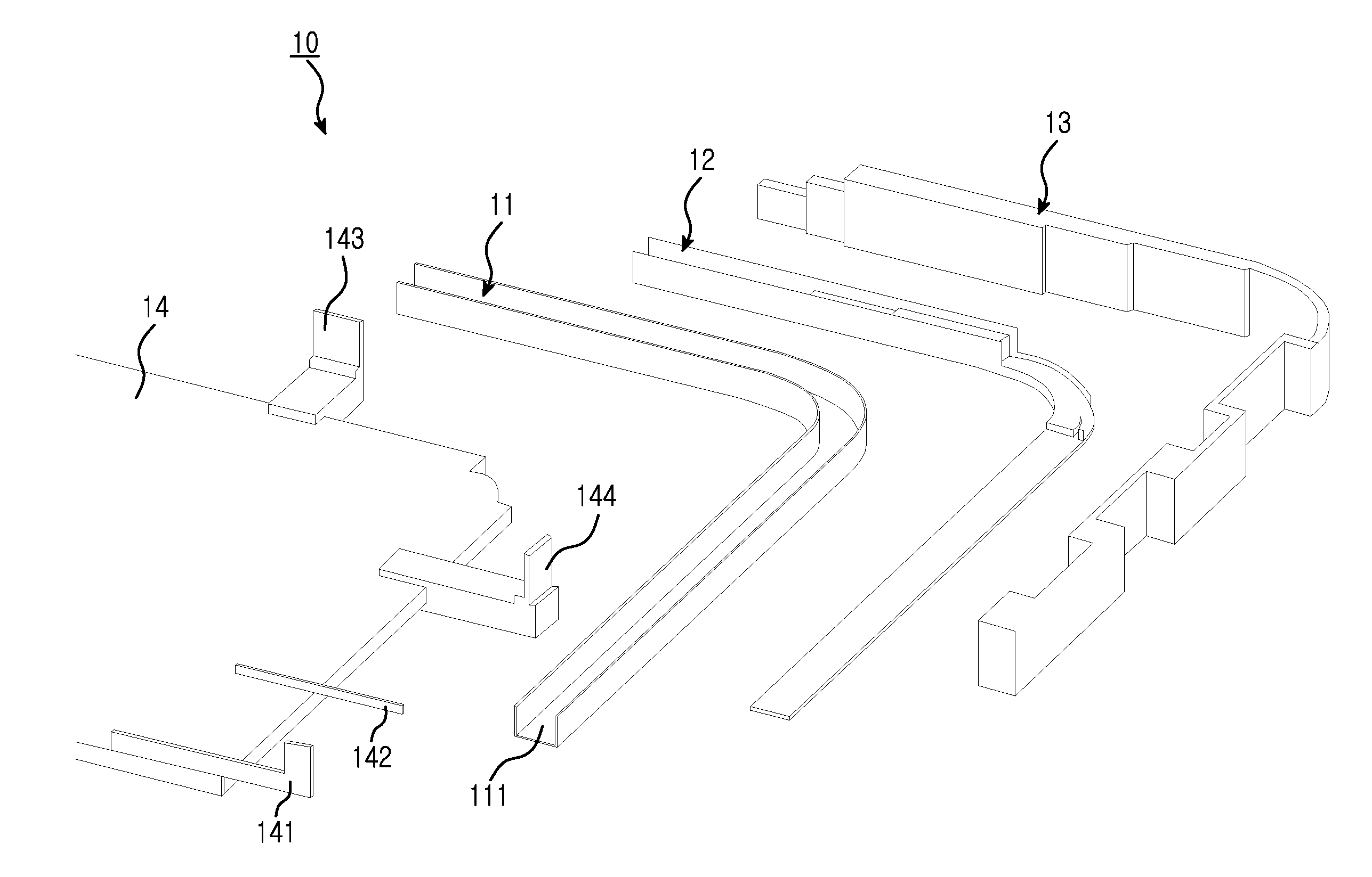
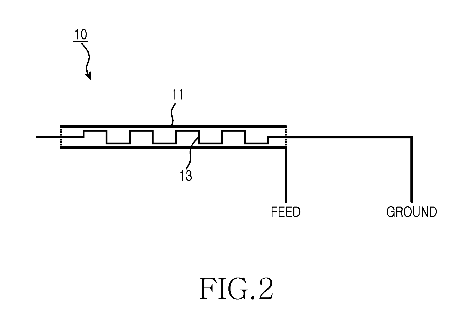
A built-in antenna of a portable terminal and a method of forming the same are provided. The built-in antenna includes a first conductor having a specific length and used for a ground, a second conductor disposed with a specific distance in parallel to the first conductor to couple with the first conductor and used for power feeding, and a separating element disposed between the first conductor and the second conductor to separate the first and second conductors. Accordingly, the built-in antenna may exhibit a smooth radiation property even if a metal construction is used in a device and thus may implement robustness improvement of the device and make the device slim and have an attractive outer appearance. In addition, a method of improving antenna efficiency may prevent deterioration of the radiation property of the antenna radiator of the related art by using simple processing, and the metal construction may be used as a radiator.

Description

PRIORITY[0001]This application claims the benefit under 35 U.S.C. §119(a) of a Korean patent application filed in the Korean Intellectual Property Office on Aug. 17, 2010 and assigned Serial No. 10-2010-0079223, the entire disclosure of which is hereby incorporated by reference.BACKGROUND OF THE INVENTION[0002]1. Field of the Invention[0003]The present invention relates to a built-in antenna and a method for improving antenna efficiency. More particularly, the present invention relates to a built-in antenna and a method for improving antenna efficiency in order to improve an antenna radiation property, to prevent radiation deterioration caused by a metal construction used to improve an outer appearance of a terminal, and to ensure mechanical robustness.[0004]2. Description of the Related Art[0005]With rapid technological advancement, a wireless communication function has been included not only in a mobile communication device but also in a portable electronic device (e.g., a media r...

Claims


Application Information

Patent Timeline
Patent Type & Authority Applications(United States)
IPC IPC(8): H01Q1/24H01P11/00H01Q9/04
CPCH01Q1/243H01Q9/42H01Q5/378H01Q5/371Y10T29/49018H01Q1/38
Inventor EOM, SANG-JINBANG, JIN-KYUKIM, HO-SAENGKIM, YONG-JINKIM, JIN-U
Owner SAMSUNG ELECTRONICS CO LTD
Why Eureka
Try Eureka