Stepping motor control circuit and analogue electronic watch

a technology of electronic watch and control circuit, which is applied in the direction of electric winding, dynamo-electric converter control, instruments, etc., can solve the problems of complex configuration and risk of erroneous memorizing of drive pulse information

Inactive Publication Date: 2012-02-23
SEIKO INSTR INC
View PDF3 Cites 7 Cited by
  • Summary
  • Abstract
  • Description
  • Claims
  • Application Information

AI Technical Summary

Benefits of technology

[0008]It is an aspect of the present application to achieve detection of a source voltage without providing a voltage detection circuit and allow a drive stop while holding correct drive pulse information when the source voltage is lowered to a predetermined level or below.
[0009]According to the application, there is provided a stepping motor control circuit including: a power source; a rotation detection device configured to detect an induced signal generated by the rotation of a rotor of a stepping motor and detect the state of rotation of the stepping motor according to whether or not the induced signal exceeds a predetermined reference threshold voltage in a predetermined detection segment; and a drive control device configured to select any one of drive pulses having energies different from each other according to the result of detection detected by the rotation detection device and control the driving of the stepping motor with a predetermined polarity, wherein the detection segment is divided into a plurality of detection segments, and the drive control device controls to stop the driving of the stepping motor in a state in which the polarity of the drive pulse to be used for restarting the driving after the voltage of the power source is restored to a voltage exceeding the predetermined voltage is known when the power source is determined to be lowered to a predetermined voltage value or below on the basis of a pattern of the segments in which the rotation detection device detects the induced signal exceeding the predetermined reference threshold voltage when the stepping motor is driven by the drive pulse having a predetermined energy.
[0010]According to an analogue electronic watch in the embodiment of the application, the analogue electronic watch includes the stepping motor configured to rotate time-of-day hands and a stepping motor control circuit configured to control the stepping motor and is characterized in that the stepping motor control circuit is employed as the stepping motor control circuit.
[0011]The motor control circuit according to the application enables detection of a source voltage without providing a voltage detection circuit and allows a drive stop while holding correct drive pulse information when the source voltage is lowered to a predetermined level or below.
[0012]According to the analogue electronic watch in the application, since the source voltage can be detected without providing the voltage detection circuit and the driving can be stopped in a state of holding the correct drive pulse information when the source voltage is lowered to the predetermined voltage or below, the driving can be started by the correct drive pulse when the source voltage is restored, so that correct clocking is achieved.

Problems solved by technology

However, since a voltage detection circuit is employed, there is a problem of complex configuration.
In addition, in an electronic watch having a secondary battery as represented by a solar energy powered watch, a stop of clocking resulted from lowering of source voltage of a movement may be performed in a state in which clocking is unstable due to variations of the movement, so that there is a risk of erroneous memorization of drive pulse information when the clocking is stopped.

Method used


Image

  • Stepping motor control circuit and analogue electronic watch
  • Stepping motor control circuit and analogue electronic watch
  • Stepping motor control circuit and analogue electronic watch

Examples


first embodiment

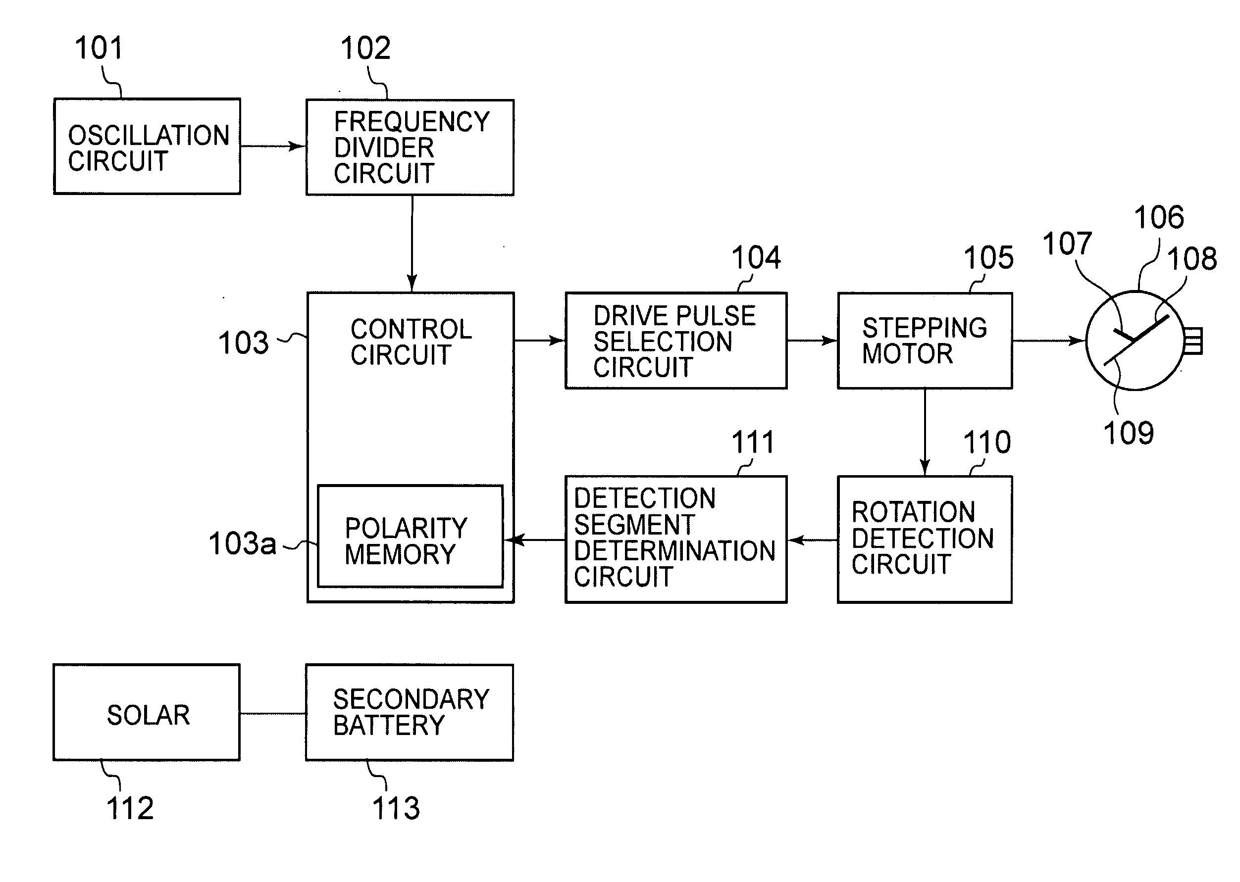
[0024]FIG. 1 is a block diagram of an analogue electronic watch using a stepping motor control circuit according to the invention, and shows an example of an analogue electronic wrist watch.

[0025]In FIG. 1, the analogue electronic watch includes an oscillation circuit 101 configured to generate signals of a predetermined frequency, a frequency divider circuit 102 configured to divide the frequency of the signals generated by the oscillation circuit 101 and generate a time signal which serves as a reference when counting the time, a control circuit 103 configured to perform control of respective electronic circuit elements which constitute the electronic watch and control of drive pulse change, a drive pulse selection circuit 104 configured to select and output a drive pulse for rotating a motor on the basis of a control signal from the control circuit 103, a stepping motor 105 configured to be rotated by the drive pulse from the drive pulse selection circuit 104, and an analogue dis...

second embodiment

[0090]FIG. 6 is a block diagram of an analogue electronic watch using a motor control circuit according to the invention showing an example of an analogue electronic wrist watch and the same components as in FIG. 1 are designated by the same reference numerals.

[0091]In FIG. 6, the control circuit 103 includes a polarity determining unit 103b which constitutes a polarity determining device. The polarity determining unit 103b has a function to determine the polarity of the correction drive pulse P2 when driven by the correction drive pulse P2. When stopping the driving as a result of lowering of the voltage of the secondary battery 113, the control circuit 103 controls to stop driving forcedly after having performed the driving of the stepping motor 105 by the drive pulse having the predetermined polarity, which is specified in advance.

[0092]FIG. 7 is a flowchart showing the action of the stepping motor control circuit and the analogue electronic watch according to the second embodime...

third embodiment

[0101]FIG. 8 is a block diagram of an analogue electronic watch using a motor control circuit according to the invention showing an example of an analogue electronic wrist watch and the same components as in FIG. 1 are designated by the same reference numerals.

[0102]In FIG. 8, the control circuit 103 includes an irregular movement controller 103c which constitutes an irregular movement control device. The irregular movement controller 103c has a function to control the driving of the stepping motor 105 in a mode different from the mode at the time of normal driving when predetermined conditions such that the state of rotation of the stepping motor 105 becomes a predetermined state, which will be described in detail later. Here, the normal driving is an action to rotate the stepping motor 105 at a constant predetermined cycle so as to display the time of day by driving the time-of-day hands 107 to 109 to clock at a constant predetermined cycle (for example, one-second cycle). By driv...


PUM


Abstract

The invention is intended to achieve detection of a source voltage without providing a voltage detection circuit and allow a drive stop while holding correct drive pulse information when the source voltage is lowered to a predetermined level or below. A detection segment for detecting the state of rotation of a stepping motor is divided into a plurality of segments and, when a pattern of an induced signal detected in the respective segments is a pattern which indicates that the voltage of a secondary battery is lowered to the predetermined voltage or below, the control circuit memorizes a polarity of the drive pulse used in the last driving in a polarity memory and stops the driving of the stepping motor. When the voltage of the secondary battery is restored to the predetermined voltage or higher, the driving is restarted by a main drive pulse having a polarity opposite from the polarity memorized in the polarity memory.

Description

BACKGROUND OF THE INVENTION[0001]1. Field of the Invention[0002]The present invention relates to a stepping motor control circuit and an analogue electronic watch using the stepping motor control circuit.[0003]2. Description of the Related Art[0004]In the related art, a stepping motor including a stator having a rotor storage through hole and a positioning portion for determining a stop position of a rotor, the rotor disposed in the rotor storage through hole, and a coil, and being configured to rotate the rotor by causing the stator to generate a magnetic flux by supplying alternating signals to the coil and stop the same at a position corresponding to the positioning portion is used in an analogue electronic watch, for example.[0005]A method employed as a method of controlling the stepping motor is a correction drive system configured to detect whether or not the stepping motor is rotated by detecting an induced signal generated in the stepping motor when the stepping motor is dri...

Claims


Application Information

Patent Timeline
Patent Type & Authority Applications(United States)
IPC IPC(8): H02P8/26G04C3/14
CPCG04C3/143H02P8/26H02P6/182G04G19/12
Inventor MANAKA, SABUROTAKAKURA, AKIRAHONMURA, KEISHIYAMAMOTO, KOSUKESAKUMOTO, KAZUMIOGASAWARA, KENJISHIMIZU, HIROSHI
Owner SEIKO INSTR INC
Why Eureka
Try Eureka