Multi-Contact Connector System

a multi-contact, connector technology, applied in the manufacture of contact parts, coupling device details, coupling device connections, etc., can solve the problems of increasing the exposure to sweat, corrosion of cochlear stimulators and related medical devices, and limited life of typical contacts, so as to improve the self-cleaning effect, increase the effective length of wipes, and high density contact

Inactive Publication Date: 2012-02-23
ADVANCED BIONICS AG
View PDF5 Cites 5 Cited by
  • Summary
  • Abstract
  • Description
  • Claims
  • Application Information

AI Technical Summary

Benefits of technology

[0009]The connector mechanism resembles a cam (male side) and cam follower (female side) mechanism. As used herein, the term “cam” means a curved wedge movable about an axis, which may be an axis of the cam itself or of a first connector of which it is a part, which forces contacts of the first connector against contacts of a second connector during rotation about the axis. In one embodiment, the cam comprises fixed metal contacts, creating a high density contact device with key and locking features. In one embodiment, the cam follower comprises a flex circuit held in tension around the perimeter of the cam. Both ends of the flex circuit are fixed to the connector housing and held in tension with a spring, such as an elastomeric spring. When the first connector and the second connector are rotated relative to each other about a mutual axis, the tension provided by the spring forces electrical contact between the cam and cam follower contacts throughout a customizable range of rotational movement. By not using the electrical contact itself to supply the spring force to maintain contact, the problem of fatigue in connectors known in the art can be eliminated. The customizable range of rotational movement can be designed to vary the self cleaning action of the wiping contacts. Instead of only adjusting wiping force to improve the self cleaning action, the connector designer may design the rotational range to increase the effective length of the wipe. The customizable range of rotation also increases design flexibility and / or reliability of the connection during vibration, since the first and second connectors may be allowed to rotate and maintain function during vibration about the axis.
[0010]The connector structure provides greater contact area than other contact designs, thereby increasing reliability. The compact size of the connector allows a size reduction of external hardware, increasing the aesthetic appeal and reducing weight. The compact size and contact density of the connector improve diagnostic tool usability, allowing analog and digital data streams to travel over one connection instead of through multiple cables.
[0011]A male connector and a female connector together provide the necessary mechanical stability. A strategically positioned sealing ring ensures a complete seal from the external environment.
[0012]Furthermore, the robust design is easily and efficiently manufactured at low cost with regard to both materials and labor.
[0013]The connector is easy to use by simply plugging the male connector into the female connector and twisting to make contact and lock.

Problems solved by technology

The sound processor is powered by batteries that typically have a limited life before they need to be recharged or replaced.
While some sound processors are carried by the user on a belt or in a pocket, others are worn behind the ear (BTE), greatly increasing the exposure to sweat.
A particular problem associated with cochlear stimulators and related medical devices is corrosion.
When sweat, bodily fluids, and other contaminants come in contact with the battery terminal or an accessory's electrical contacts, corrosion occurs, which, left unchecked, would eventually disable the system, or at least disable the accessory.
Another problem is medical device stability and ability to withstand vibration.

Method used


Image

  • Multi-Contact Connector System
  • Multi-Contact Connector System
  • Multi-Contact Connector System

Examples


Embodiment Construction

[0039]The following description is of the best mode presently contemplated for carrying out the invention. This description is not to be taken in a limiting sense, but is made merely for the purpose of describing the general principles of the invention. The scope of the invention should be determined with reference to the claims.

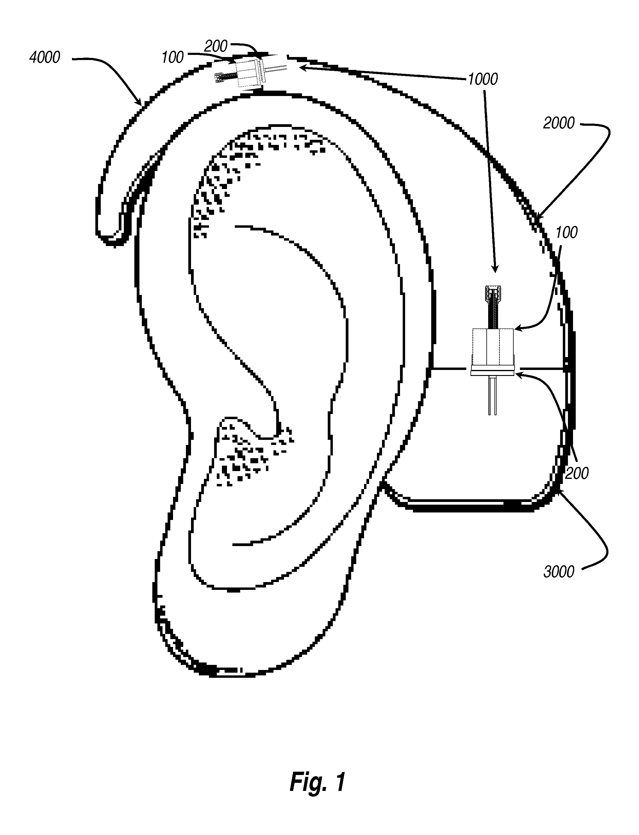
[0040]FIG. 1 shows a Behind-The-Ear (BTE) sound processor 2000 utilizing the multi-contact connector system 1000 of the present invention to provide a mechanical and electrical connection for a battery 3000 and for an earhook 4000. The earhook 4000 is arched and hooks in front of the ear, and is removably attached to the BTE sound processor 2000. The BTE sound processor 2000 continues the arch and is positioned behind the ear. The battery 3000 is removably attached to the bottom of the BTE sound processor 2000. Various batteries of different sizes may be interchangeably attached to the BTE sound processor, depending upon the needs of a user. Likewise, variou...


PUM

PropertyMeasurementUnit
widthaaaaaaaaaa
widthaaaaaaaaaa
tensionaaaaaaaaaa

Abstract

A connector system for Behind-The-Ear (BTE) hearing devices provides a means to detachably connect a variety of accessories to a sound processor, including batteries, earhooks, telecoils, auxiliary microphones, FM receivers, and input jacks for miscellaneous devices. The present invention provides an efficient and economical sealing connection, eliminating the introduction of sweat, body fluid and other contaminants into the connection area, which otherwise would result in corrosion and eventually disable the connected device. A wiping contact formed by a configuration of cam contacts and a flex circuit with a configuration of corresponding contacts is combined with a rotational engagement mechanism to create a vibration-resistant high contact density connector that is moisture proof when engaged.

Description

RELATED APPLICATIONS[0001]The present application claims priority to U.S. Provisional Patent Application No. 61 / 175,451 by William Dai et al., filed on May 4, 2009, and entitled “MULTI-CONTACT CONNECTOR SYSTEM,” the contents of which are hereby incorporated by reference in their entirety.BACKGROUND OF INVENTION[0002]The present invention relates to hearing devices for aiding the hearing impaired and the profoundly deaf, and more particularly to a multi-contact connector system providing electrical and mechanical connection between an external sound processor and a battery, earhook, or other accessory desired to attach to the sound processor. The connector system of the present invention is useful for conventional hearing aids and for cochlear stimulation systems employing Behind-The-Ear (BTE) and body worn sound processors, and for other devices requiring a mechanically stable and robust sealing connector having multiple contacts.[0003]Implantable Cochlear Stimulation (ICS) systems ...

Claims


Application Information

Patent Timeline
Patent Type & Authority Applications(United States)
IPC IPC(8): H01R13/44H01R43/16
CPCH01R13/245H01R13/5202H04R25/556H01R2201/12Y10T29/49204H04R25/607
Inventor DAI, WILLIAM A.TZIVISKOS, GEORGE
Owner ADVANCED BIONICS AG
Why Eureka
Try Eureka