
Co-molded, focused weighted, dimple arrayed hockey sticks and other composite structures

a composite structure and focused weight technology, applied in the field of composite structures, to achieve the effect of saving weight in lightening

Inactive Publication Date: 2012-02-23
BAUER HOCKEY
View PDF5 Cites 30 Cited by
  • Summary
  • Abstract
  • Description
  • Claims
  • Application Information

AI Technical Summary

Benefits of technology

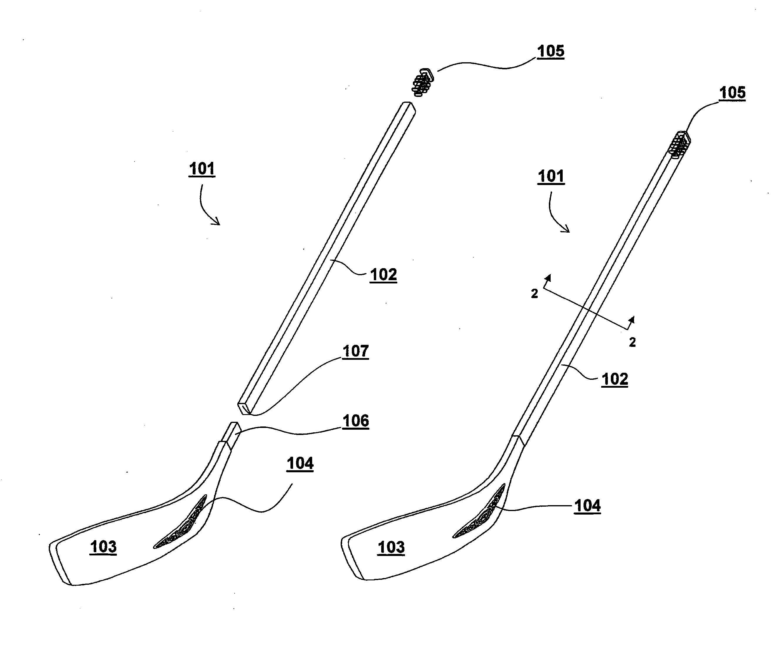
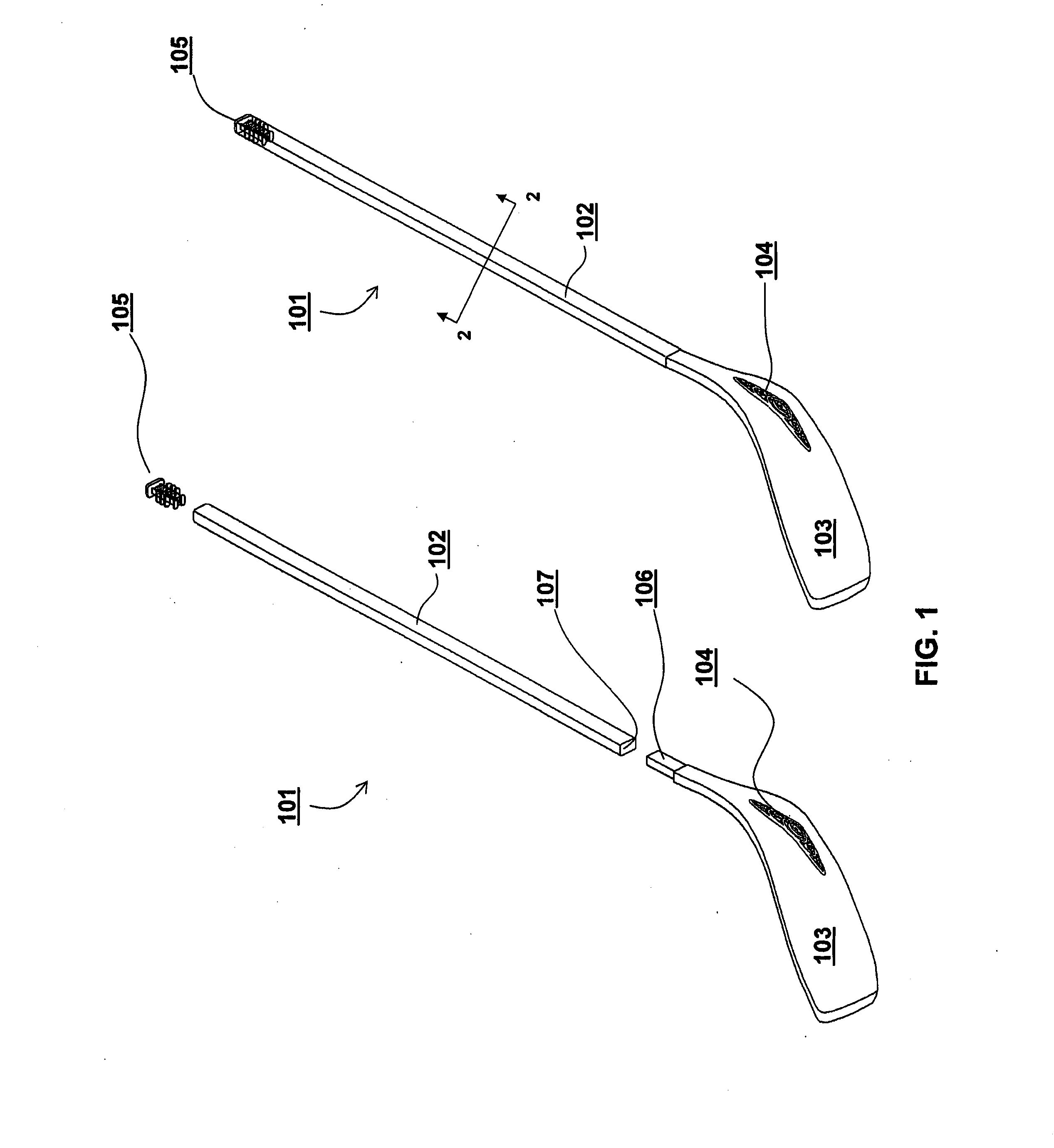
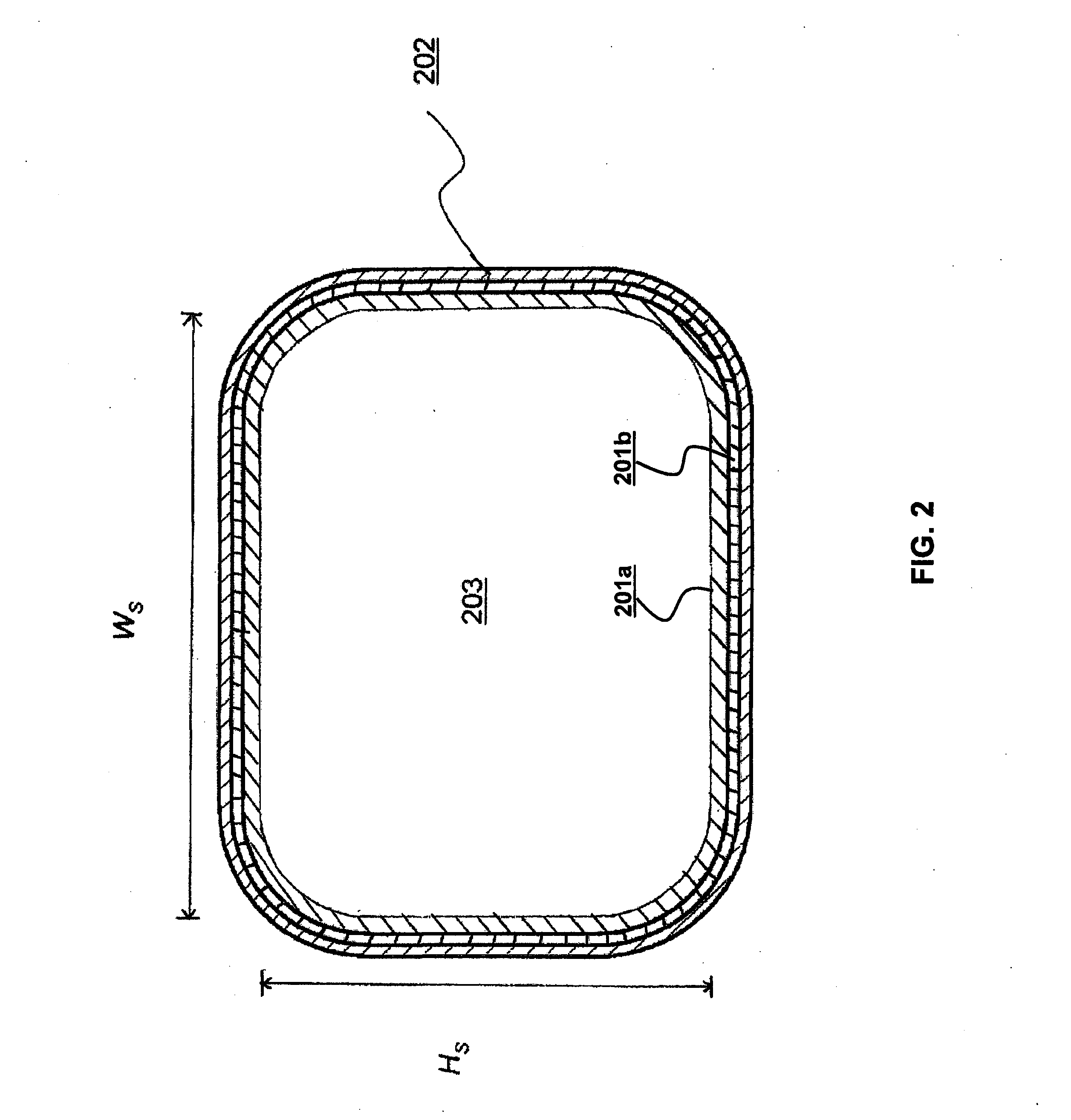
[0010]One aspect is directed to a composite structure such as hockey stick blades constructed of fibers disposed within a hardened resin matrix encapsulating one or more core elements such as a light foam (e.g., polyurethane foam), wherein the blade further includes one or more high density components (e.g. metal) positioned externally on the blade. The high density components may be positioned on the front or back of the blade at the heel region or other regions of the blade such as the mid section or toe region thereby creating a focused weight distribution on the blade. A polyurethane elastomer or some other suitable polymer or material may encapsulate the high density components, for instance, to serve as a means to secure the high density components relative to one another and / or in the desired location on the blade. Branding, logo, or other information may be incorporated with the high density element and may also be encapsulated within the polymer. The information may be part of the high density element and / or separate therefrom. The encapsulating polymer may be clear or translucent throughout the component or in one or more regions to allow the high density weights and / or the logo / branding / information to be suitably visible to the user to the extent desired. For example, when both high density component(s) and logo / branding / information elements are encapsulated within the polymer to create a weighted domed logo assembly that is comprised of embedded weights in combination with a logo, such a construct is capable of providing both a desired focused weight distribution as well as appealing and visible branding of the technology to the user in a desirable appearance.
[0014]Another aspect is directed to a weight-adjustable end-plug dimensioned to be insertable into a tubular shaft, such as a hockey stick. The weight-adjustable end-plug includes an end-plug unit and one or more weighted components insertable into the end-plug unit. The end-plug unit may include one or more chambers to receive and secure the one or more weighted components. The end-plug unit may also include multiple fins that extend laterlly from opposing surfaces of the end-plug unit. Once the weight-adjustable end-plug unit is inserted into a tubular hockey stick shaft, the multiple fins flex against the side walls of the hockey stick shaft to secure the weight-adjustable end-plug in its position. The weight-adjustable end-plug allows a hockey player to add and remove weights from the end of the hockey stick shaft and thereby adjust the swing weight of the hockey stick.

Problems solved by technology

Notably, such finishing processes are applied to the hardened surface of the composite structure and are not integrated or incorporated into the molding process.

Method used


Image

  • Co-molded, focused weighted, dimple arrayed hockey sticks and other composite structures
  • Co-molded, focused weighted, dimple arrayed hockey sticks and other composite structures
  • Co-molded, focused weighted, dimple arrayed hockey sticks and other composite structures

Examples


Embodiment Construction

[0035]Preferred embodiments of the various inventive technology disclosed herein will now be described with reference to the drawings. To facilitate description, any reference numeral designating an element in one figure will designate the same element if used in any other figure. The following description of preferred embodiments is only exemplary. The present invention is not limited to these embodiments, but may be realized by other implementations. Furthermore, in describing preferred embodiments, specific terminology is resorted to for the sake of clarity. However, the invention is not intended to be limited to the specific terms so selected, and it is to be understood that each specific term includes all equivalents. Moreover, while various aspects of the inventive technology are disclosed and described without specific reference to other aspects elsewhere disclosed or described, it should be understood that all of the various aspects and implementations can be combined in any...


PUM

PropertyMeasurementUnit
Temperatureaaaaaaaaaa
Weightaaaaaaaaaa
Densityaaaaaaaaaa

Abstract

Unique composite structures are disclosed that include focused adjustably weighted end plugs, co-molded focused weighted and non-weighted logo / branding components and / or dimple arrays. A representative composite hockey stick having a tubular hollow shaft, a blade, and a weight-adjustable end-plug is disclosed. The blade includes one or more weighted regions in the form of a focused weight system co-molded to an external surface of the blade. The blade may also include one or more co-molded non-weighted logo / branding components and / or one or more dimple arrays on the front and / or back face of the blade. Methods and suitable materials for constructions of the various components and composite constructs are also disclosed.

Description

CROSS REFERENCE TO RELATED APPLICATIONS[0001]This application claims the benefit of U.S. Provisional Application No. 61 / 367,332, filed Jul. 23, 2010, which is incorporated herein by reference in its entirety.FIELD OF THE INVENTION[0002]The field of the present invention generally relates to composite structures including sporting implements such as hockey sticks and component structures thereof.BACKGROUND OF THE INVENTION[0003]Composite structures are generally comprised of fibers (aligned in one or more defined orientations and / or randomly oriented) disposed within a hardened resin matrix. Their manufacture typically involves overlaying one or more plies of fibers in a desired manner relative to one another to create an uncured pre-form construct. The pre-form construct is then cured using a mold (e.g., external and / or internal molds) and perhaps a compression or expansion bladder to facilitate the curing and molding process. The curing process hardens the resin, which is either im...

Claims


Application Information

Patent Timeline
IPC IPC(8): A63B59/14B29C43/18
CPCA63B59/0014A63B59/14B29K2075/00B29C70/46B29C70/865A63B2209/023A63B2102/24A63B59/70A63B60/08B29C70/86B29K2675/00A63B60/24A63B60/16A63B60/06A63B60/10
Inventor ALLEN, PATRICKGOLDSMITH, EDWARDIA, CITRA A.MOUNTAIN, MIKESNOW, MIKE
Owner BAUER HOCKEY
Learn More