
Twisted ribbon wire guidewire coil

a technology of guidewires and ribbon wires, applied in the field of medical guidewires, can solve problems such as difficult to achieve characteristics, and achieve the effects of strong coils, high value and usefulness, and precise feedback

Active Publication Date: 2012-02-23
ABBOTT CARDIOVASCULAR
View PDF0 Cites 23 Cited by
  • Summary
  • Abstract
  • Description
  • Claims
  • Application Information

AI Technical Summary

Benefits of technology

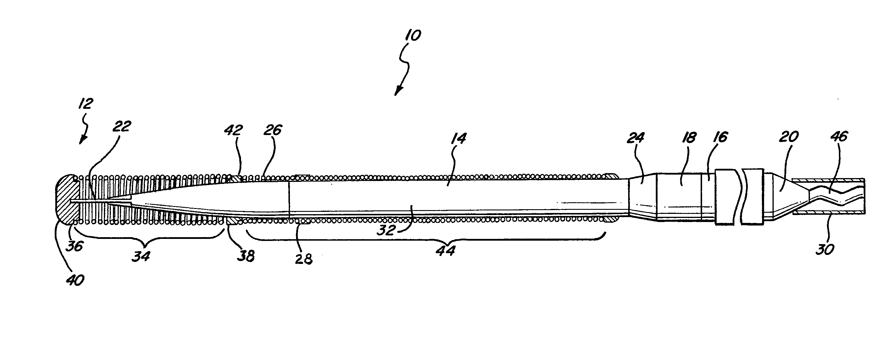
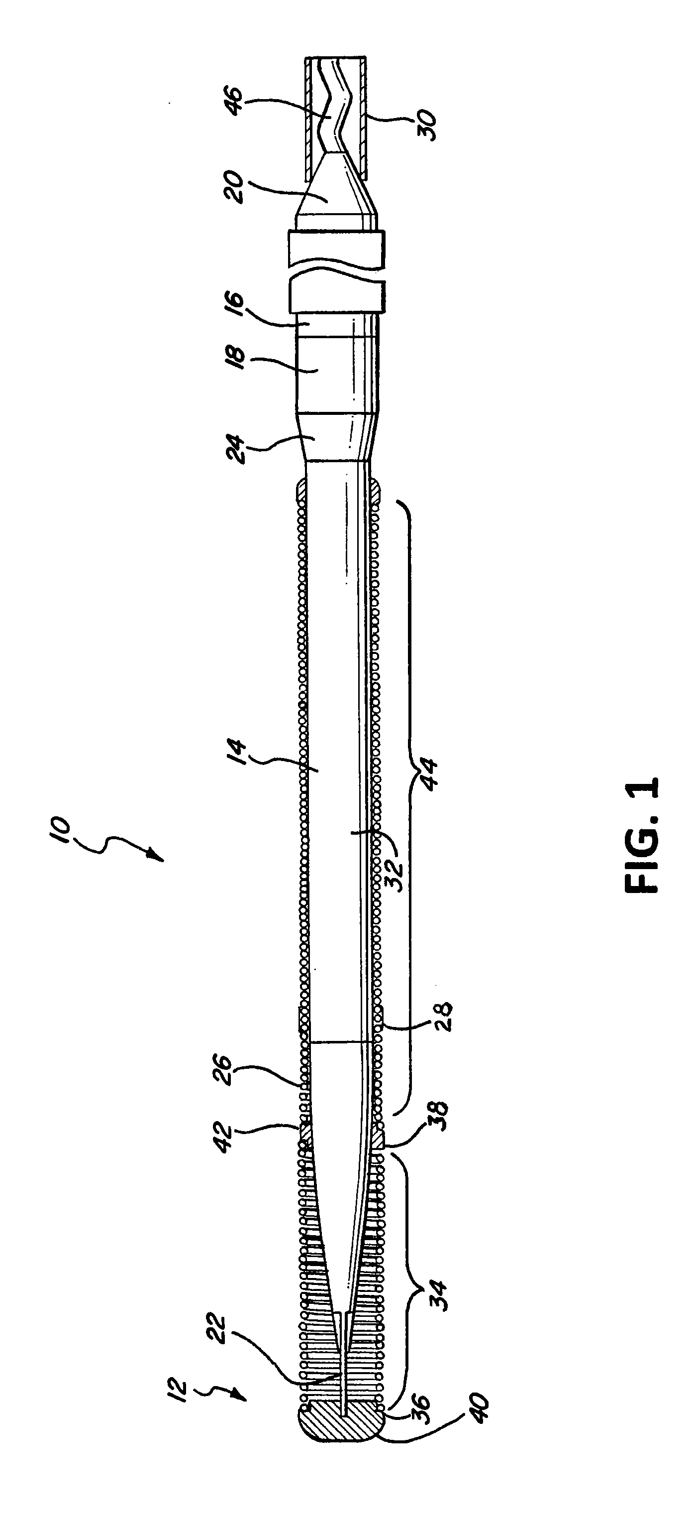
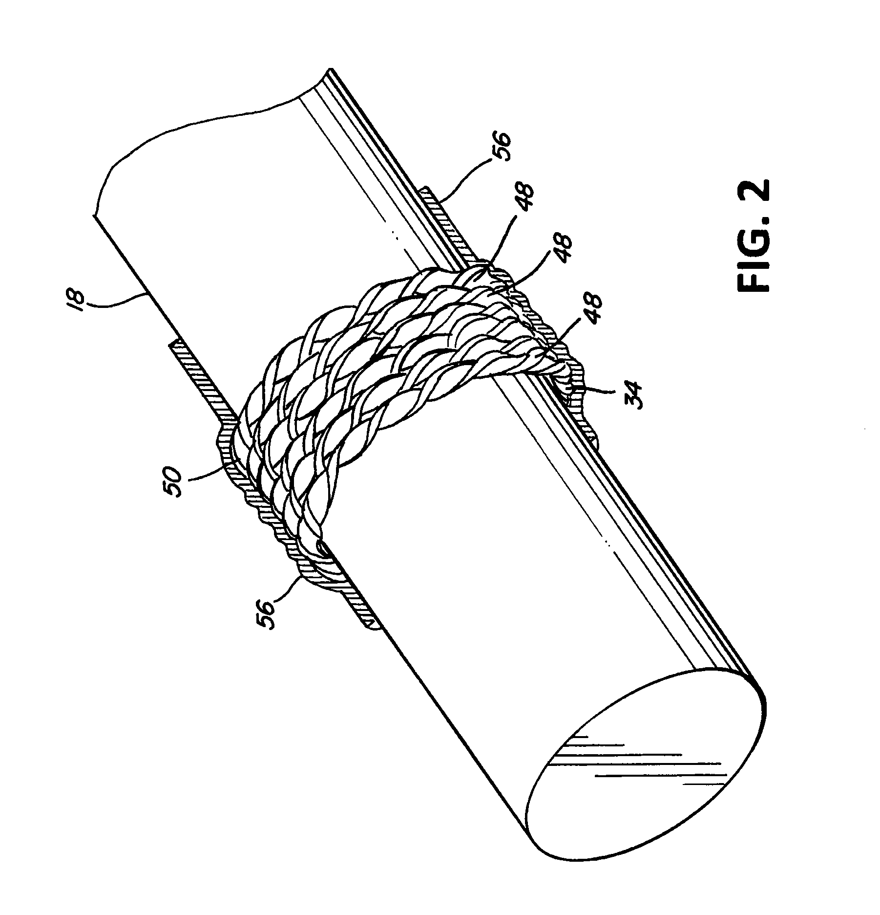
[0012]The twisted, flat ribbon coil even when covered with one or multiple polymeric coating layers still retains its undulating circumferential profile. When the physician or cardiologist advances and torques the guidewire at the proximal end, the undulating surface profile at the distal end of the guidewire as it moves along the interior of the vessel provides precise, tactile feedback to its user. This enables the physician or cardiologist to more precisely maneuver and deftly negotiate a patient's tortuous vasculature to ultimately locate the guidewire accurately and more easily at the treatment site. This improved feel is highly valued and useful to cardiologists and physicians who use such guidewires in the field.
[0013]Typically, the tip coil only serves to add a uniform profile and form an atraumatic surface to the otherwise rigid and irregularly shaped, floppy distal end of the guidewire core. On the other hand, the present invention twisted, flat ribbon wire coil adds mass to the coil leading to a stronger coil. A stronger coil enables designers and engineers to remove mass and reduce the size of the guidewire core. A lower mass or a slimmer guidewire core at its distal end, even though still pushable as before, now has a distal core section that is even more gentle and atraumatic to minimize possible injury to the vessel intima. Furthermore, when the mass of the guidewire is shifted to the coil, the distal core section can incorporate engineering improvements such as a parabolic grind to impart a linear change in stiffness. The linear change in stiffness at the distal end of the guidewire then enhances the ability of the cardiologist to precisely control and manipulate the distal end.
[0014]The present invention twisted, flat ribbon wire coil in adding mass to the coil allows for greater variation in the range of tip stiffnesses beyond what would be normally achievable using the conventional methods of changing the core grind or materials.

Problems solved by technology

These characteristics are difficult to achieve, as one tends to negate the other.
This can be problematic for guidewires designed for the peripheral arteries, such as those found within the legs and arms, because the size of the diagnostic and therapeutic devices used in these arteries are typically large, requiring a larger outer diameter guidewire, which can be stiffer and less flexible than coronary wires due to its size.

Method used


Image

  • Twisted ribbon wire guidewire coil
  • Twisted ribbon wire guidewire coil
  • Twisted ribbon wire guidewire coil

Examples


Embodiment Construction

[0022]In FIG. 1, a guidewire 10 with a distal tip 12 is shown which has features of a preferred embodiment of the present invention. The guidewire 10 has an elongate core 14 with a proximal core section 16 and a distal core section 18. The proximal core section 16 terminates proximally in a proximal end 20, and the distal end terminates in a distal end 22. The distal end 22 preferably has a substantially round cross-section, but in the embodiment shown, is flattened and is malleable in order to facilitate shaping of the distal tip of the guidewire 10 by the user. The proximal core section 16 of the elongate core member 14 can have an outer diameter of about 0.017 inch (0.4 mm) to about 0.030 inch (0.8 mm), but preferably has an outer diameter of about 0.020 inch (0.5 mm) to about 0.027 inch (0.7 mm).

[0023]The elongate core 14 may be formed of stainless steel, specifically 304V stainless steel, pseudoelastic or superelastic nickel-titanium (NiTi) alloys, or combinations thereof such ...


PUM

PropertyMeasurementUnit
outer diameteraaaaaaaaaa
thicknessaaaaaaaaaa

Abstract

A medical guidewire having distal tip coil that includes a twisted ribbon wire construction. The distal tip coil is mounted to the distal end of the distal core section of the guidewire. The coil is made from a flat ribbon wire with a polygonal, preferably rectangular, cross-section that is twisted along the length of the wire. The twisted, flat ribbon wire creates a tip coil that has a roughened, undulating surface at the outer circumference that, whether coated or bare, is perceptible to the physician or cardiologist when pushing or torquing the guidewire in an interventional procedure.

Description

BACKGROUND[0001]This invention relates to the field of medical guidewires for advancing intraluminal devices such as stent delivery catheters, balloon dilatation catheters, atherectomy catheters and the like within body lumens.[0002]The most common method for insertion of percutaneous catheters is the Seldinger technique. In this procedure, a local anesthesia is delivered and a skin puncture is made proximal to the femoral or brachial artery with an obturator positioned within a cannula (sheath). Once inside the artery, the obturator is removed and a guide catheter placed into the desired position in the anatomy through the cannula. Then a guidewire is inserted through the cannula into the artery. The guidewire is then advanced into the vasculature guided by fluoroscopic imaging to the desired site. Generally, the distal tip of the guidewire is pre-shaped by manufacture or has the ability to be shaped by the physician in order to steer the guidewire to the desired location by rotati...

Claims


Application Information

Patent Timeline
Patent Type & Authority Applications(United States)
IPC IPC(8): A61M25/09
CPCA61M25/09A61M2025/09083Y10T29/49826A61M2025/09191A61M2025/09108A61M2025/09166
Inventor BROWN, DANIEL G.
Owner ABBOTT CARDIOVASCULAR
Learn More