Apparatus and methods for continuous compatibility testing of subterranean fluids and their compositions under wellbore conditions

Active Publication Date: 2012-03-01
HALLIBURTON ENERGY SERVICES INC
View PDF62 Cites 27 Cited by
  • Summary
  • Abstract
  • Description
  • Claims
  • Application Information

AI Technical Summary

Benefits of technology

[0008]The present inventions provide equipment and procedures for successively and accurately testing the compatibility of a series of wellbor

Problems solved by technology

Indeed, the materials in some mixtures may be characterized as incompatible.
Two fluids are inc

Method used


Image

  • Apparatus and methods for continuous compatibility testing of subterranean fluids and their compositions under wellbore conditions
  • Apparatus and methods for continuous compatibility testing of subterranean fluids and their compositions under wellbore conditions
  • Apparatus and methods for continuous compatibility testing of subterranean fluids and their compositions under wellbore conditions

Examples


example a

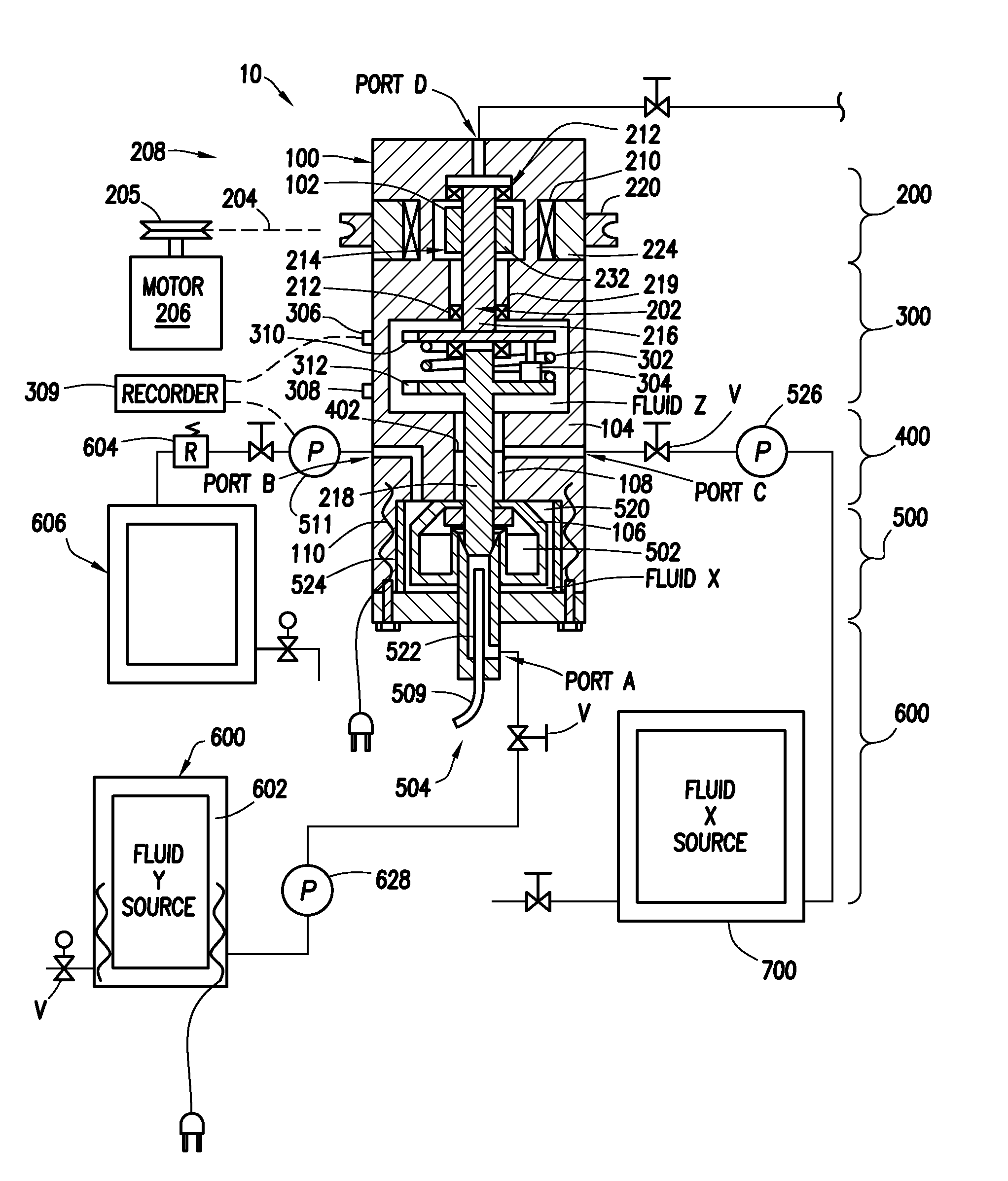
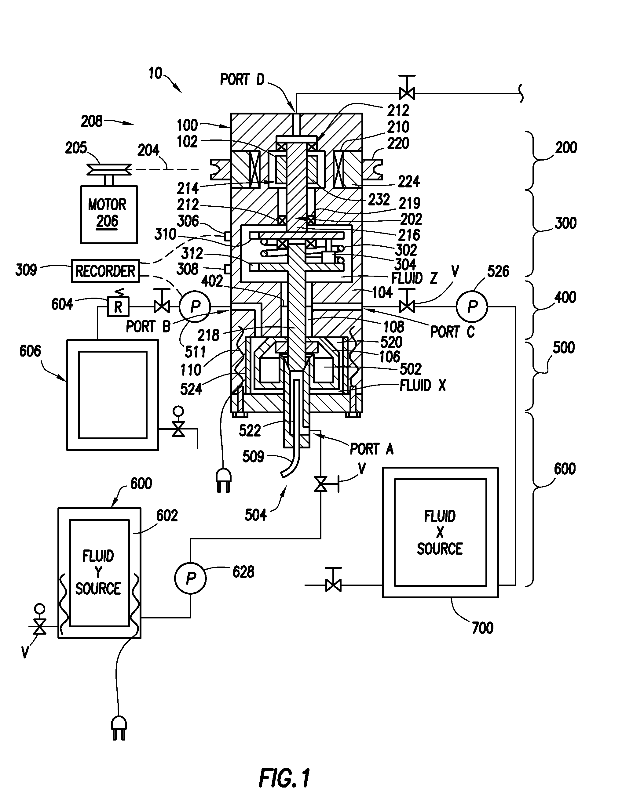
[0033]An example of a method of utilizing the test apparatus 10 will be described in reference to FIG. 1 and is illustrative of the present invention used to test a variety of proportional mixtures of test fluids and / or solids X and Y. Hydrocarbon well application examples of components of mixtures to be tested include hydrocarbon liquids and gases, acids, gels, cement, mud, proppant, sand, bauxite spacers and elastomers, clays, slag, fly ash, surfactant, polymers and the like. For example, slurries of proppant from 8 to 100 mesh can be tested. In this example, two fluids in liquid form are tested, however, a variety of proportional mixtures and slurries of two or more fluids and solids could also be tested. Indeed a single fluid could also be tested under different conditions using the present inventions.

[0034]The first step in this example is to manipulate the valves v and pump 526 to inject fluid X from reservoir assembly 700 into the lower chamber portion 106 through Port C. Inj...

example b

[0042]The testing apparatus can also be used to perform a series of tests of samples of well fluids. In this example, the reservoir assembly 600 is connected to a source of well fluids such as, for example, the drilling mud which at the time was being circulated through the well. As in example A, the ports are used to place a first test sample in the lower chamber portion 106. As described in Example “A” using the ports, a suitable second fluid is placed above the test fluid and the contents of the enclosure are brought to test conditions. The test fluid is then tested. When it is desired to test a second test sample, the second sample is pumped into the lower chamber portion 106 by displacing the first sample and to discharge it from the apparatus into waste reservoir 606. The fluids remaining in the lower chamber 106 will approach, but not completely reach, a 100% concentration of the second sample. The second sample is then tested. This process can be repeated with succession of ...

example c

[0043]The apparatus can also be used to perform continuous monitoring (testing) of a fluid as it is pumped through the lower chamber portion by pump 526. For example, a fluid being pumped into or circulated through a wellbore (or other fluid application) could be continuously sampled and the sample pumped through the lower chamber. With the motor running, the shear forces are constantly measured and recorded along with the temperature and pressure. Ideally, a pressure regulator 604 is connected to the discharge port to maintain the test pressure while the test fluid is being circulated through the lower chamber.

[0044]After the test is completed the lower chamber portion 106 is disassembled and the removable cylindrical cup 524, vanes 520 and rotating paddle assembly 502 are removed and cleaned.

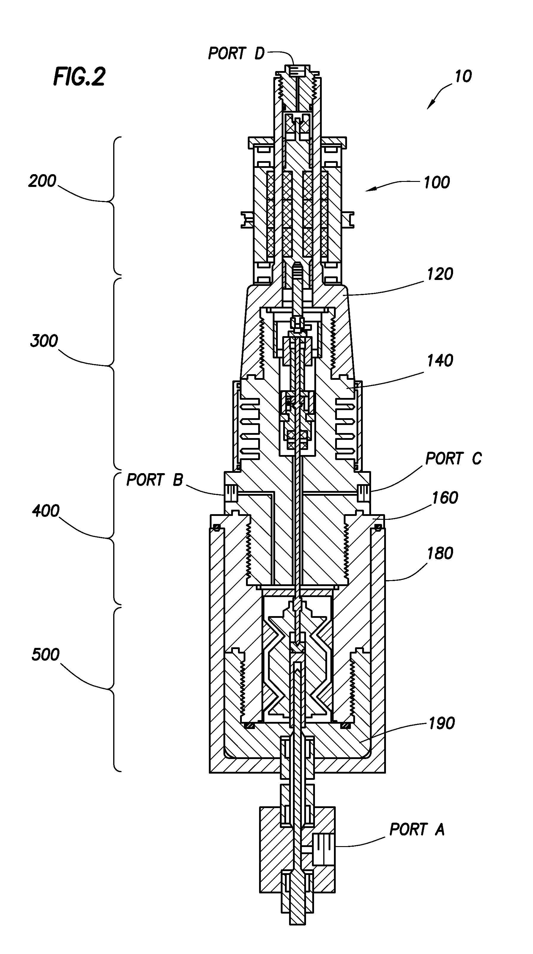
[0045]Turning now to FIG. 2, the details of another embodiment of the testing apparatus 10 will be described. In this embodiment, the pressure chamber housing assembly 100 is made up of an upp...


PUM


Abstract

Disclosed is a fluid testing device which utilizes a small, cross-section fluid interface to separate a test fluid chamber from a drive and measuring chamber. The test fluid chamber contains the test fluid and a paddle-type fluid test assembly. The drive and measuring chamber contains a second fluid and assemblies for moving the paddle and for determining the resistance movement. The two chambers are connected together by a narrow cross-section passageway allowing for continuous testing while test fluids are flowed through the test chamber and for successive testing of different samples without breaking down the device between tests. A pair of coaxial shafts extends between the test fluid chamber and the drive and measuring chamber. The shafts are connected together by a spring located in the drive chamber whereby the resistance to movement is determined by measuring the deflection in the spring. The shafts are magnetically coupled to a motor to rotate the shafts.

Description

BACKGROUND[0001]1. Technical Field[0002]The invention relates to testing apparatus and methods for conducting tests of compatibility on wellbore fluids and their contaminated mixtures and slurries under specific pressure and temperature conditions and, in particular, apparatus and methods for testing fluid mixtures and slurries for use in subterranean wellbores under simulated wellbore conditions.[0003]2. Background Art[0004]When drilling, completing, and treating subterranean hydrocarbon wells, it is common to inject materials fluid form with complex structures, such as, suspensions, dispersions, emulsions and slurries. These injected materials are present in the wellbore with materials such as water, hydrocarbons and other materials originating in the subterranean formations. The materials present in the wellbore will be referred to herein as “wellbore fluids” or “wellbore liquids”. These substances and their mixtures flow rather than plastically deform. The flow of these fluids a...

Claims


Application Information

Patent Timeline
IPC IPC(8): E21B47/06E21B47/10
CPCG01N11/14
Inventor PINDIPROLU, SAIRAM K.S.GRAY, DENNIS WILLIEGORDON, CHRISTOPHER LYNNBALARAMAN, BALASUNDARAM
Owner HALLIBURTON ENERGY SERVICES INC
Why Eureka
Try Eureka