
Pneumatic tire

a pneumatic tire and tyre technology, applied in the field of pneumatic tires, can solve the problems of increasing an electric resistance, increasing an electrical conductivity, and affecting the quality of pneumatic tires, so as to prevent a manufacturing process from getting complex, improve productivity, and form symmetrically.

Inactive Publication Date: 2012-03-01
SUMITOMO RUBBER IND LTD
View PDF4 Cites 3 Cited by
  • Summary
  • Abstract
  • Description
  • Claims
  • Application Information

AI Technical Summary

Benefits of technology

[0028]In the pneumatic tire as set forth in claim 1, there is a conducting portion on the inward side of each of a first cap portion and a second cap portion in the radial direction of the tire. Therefore, the tread rubber can be easily formed symmetrically even if the first cap portion and the second cap portion are formed in an identical profile. This helps to prevent a manufacturing process from getting complex and to improve productivity. Especially the invention according to claim 4, when the first cap portion and the second cap portion are formed substantially symmetrically with respect to the tire equator, the productivity improves more.
[0029]The conducting portion is arranged in the inside of each of the first cap portion and second cap portion in the radial direction of the tire, and the rigidity of tread rubber in the side of the first cap portion and the rigidity of tread rubber in the side of the second cap portion can be easily equalized. This can prevent a deterioration of uniformity of the tire.
[0030]When the conducting portion is smoothly convex outwardly in the radial direction of the tire and comprises an arc curved part having the above-mentioned outmost portion at the top as shown in the invention according to claim 2, even if the tread rubber wears, it can expose a new conducting portion outside both of the outmost portion in the axial direction of the tire. Therefore, a static electricity discharging efficacy can be maintained for long periods of time.
[0031]Additionally, as shown the invention according claims 7 to 9, winding the rubber strip allows to join a winding beginning and a winding terminate of the rubber strip. Therefore, uneven caused by the edges of the rubber strip can be tempered; eventually, the uniformity can be more improved.BRIEF EXPLANATION OF THE DRAWING
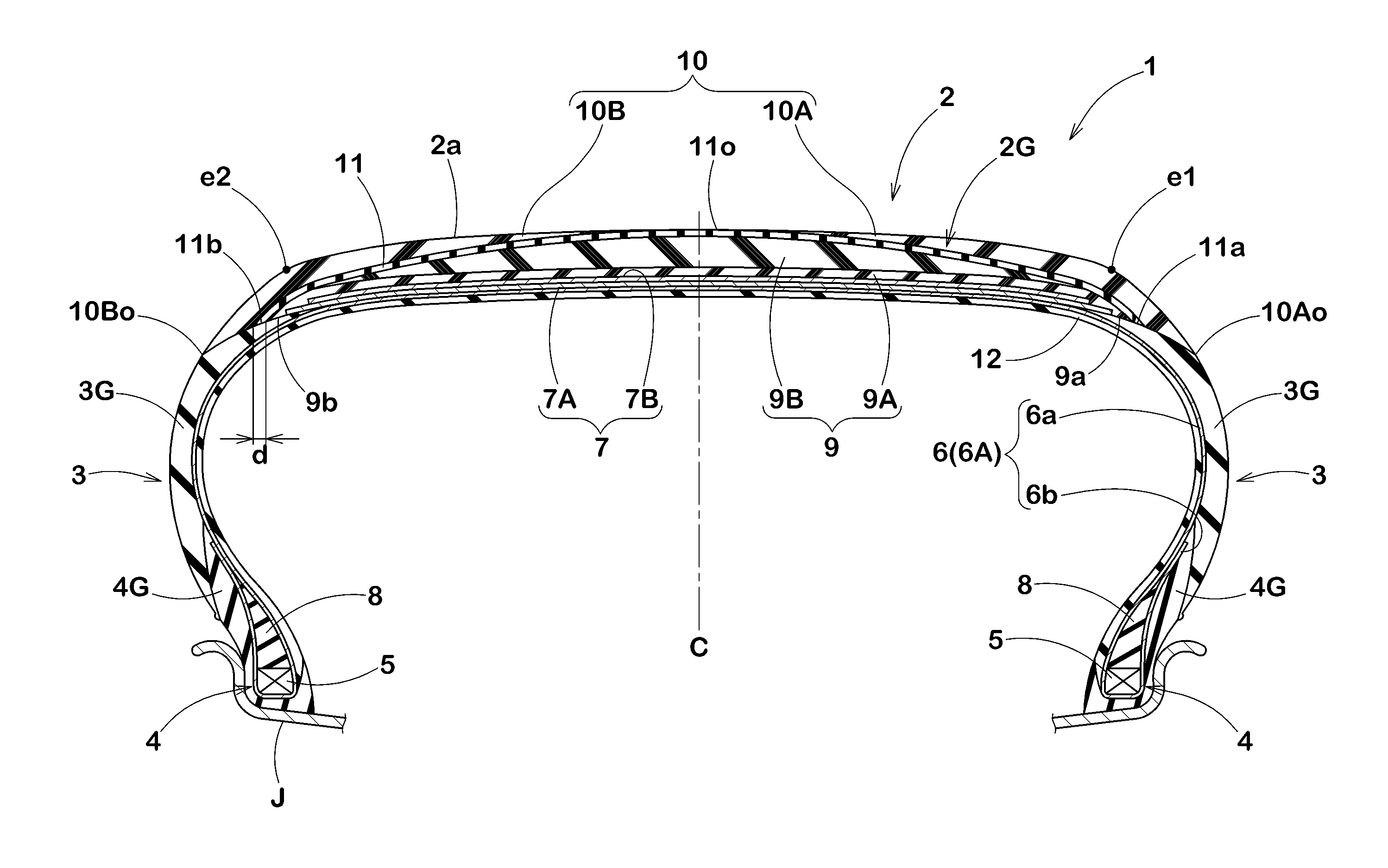
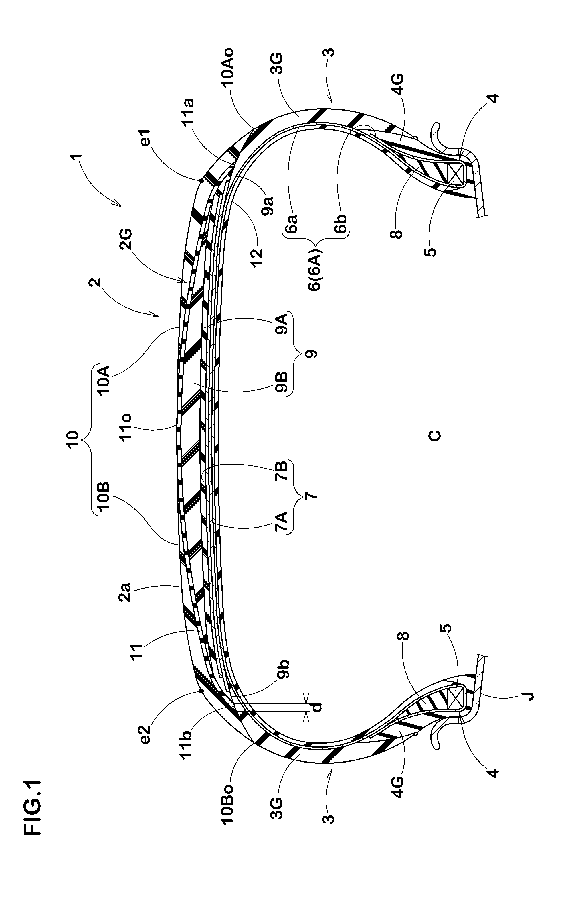
[0032]FIG. 1 A cross-sectional view of a pneumatic tire showing an embodiment of the present invention.
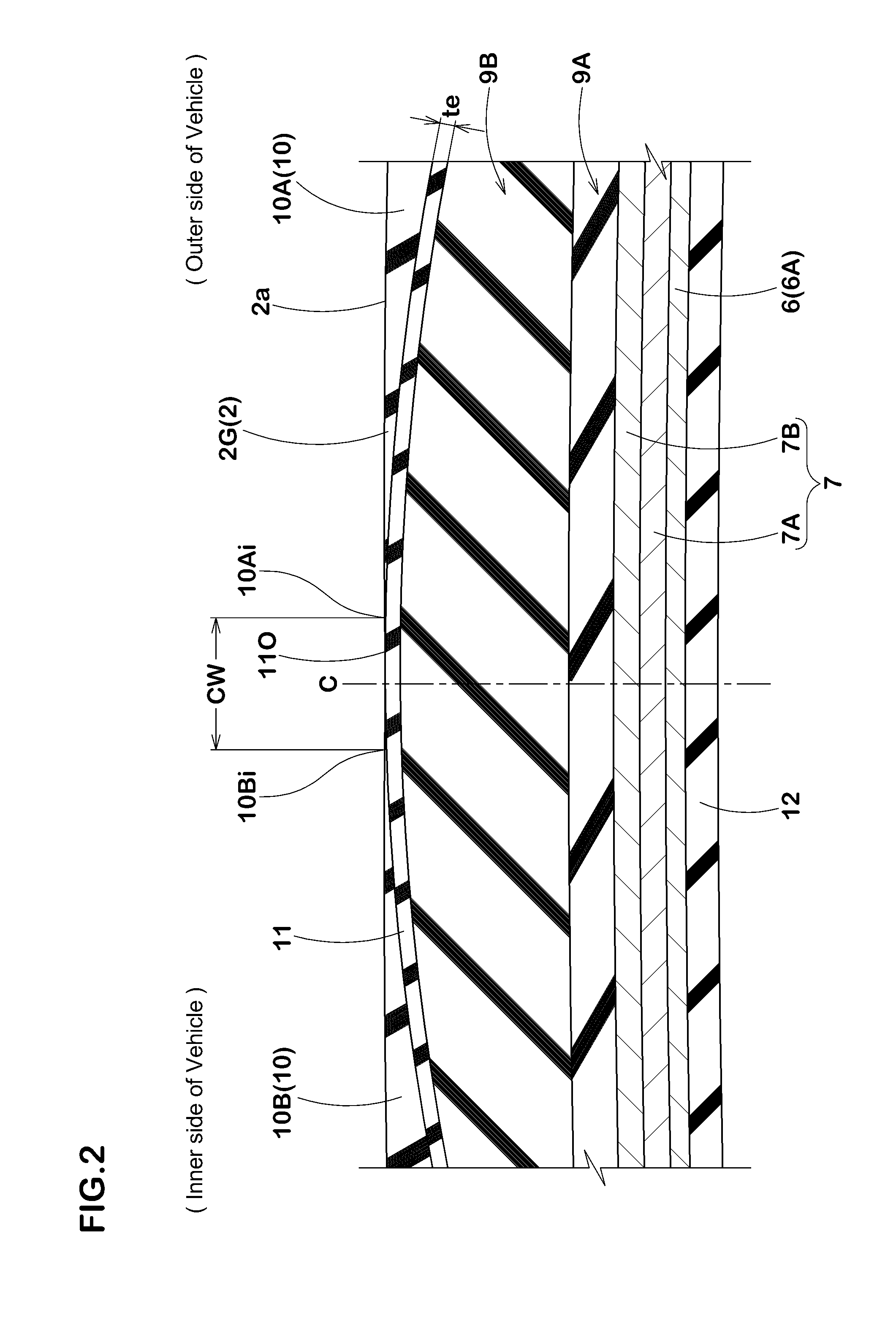
[0033]FIG. 2 A partially enlarged view of a tread portion thereof.

Problems solved by technology

However, the silica is inferior in electrical conductivity, and it increases an electric resistance of tire.
A tire having a large electric resistance accumulates the static electricity in the vehicle, and it possibly causes radio disturbance such as radio noise.
This tread rubber (a) is not sufficiently expected to diminish the rolling resistance efficacy.
Additionally, the base portion (b) is completely divided into the right and left helves, and at a time of forming the tread rubber (a), the base portion (b) is liable to move over from an applying position and the like, so that the tire uniformity tends to degrade.

Method used


Image

  • Pneumatic tire
  • Pneumatic tire
  • Pneumatic tire

Examples


example

[0123]Test pneumatic tires (Size: 215 / 45R17) having a basic structure shown in Table 1 were made, and electric resistance and uniformity of each of the tires were measured. In each example, electrically non-conductive rubber was used for a cap portion and a base portion, and electrically conductive rubber was used for a conducting portion, respectively. They were the same in composition in each example. Moreover, the tires were identical, except parameters shown in Table 1. Test method was as follows.

[0124]

[0125]As shown in FIG. 15, an electric resistance value of an assembly of the test tire and a rim J was measured according to the procedure specified by the Japan Automobile Tire manufacturers Association (JATMA) by the use of a measuring apparatus. The measuring apparatus comprises a metal plate 21 (Electric resistance value: not more than 10Ω) of which surface was polished and which was placed on an insulation plate 20 (Electric resistance value: not less than 1012Ω), a electric...


PUM


Abstract

A tread rubber 2G comprises a base portion 9 made of electrically non-conductive rubber compounding silica and having a width substantially equal to a width of the tread reinforcing-cord layer 7; a conducting portion 11 made of the electrically conductive rubber, covering a radially outer surface of the base portion 9 and extending in the axial direction of the tire, and protruding both end portions 11a and 11b outwardly from the base portion 9 so as to connect the both end portions with tire members Ty electrically conducted to a rim J at a state of mounting the tire on the rim; and a cap portion 10 made of electrically non-conductive rubber compounding silica and disposed outside the conducting portion 11 in the radial direction of the tire and forming a major part of a ground contact surface 2a.

Description

TECHNICAL FIELD[0001]The present invention relates to a pneumatic tire enabling to discharge static electricity from a vehicle into a road surface.BACKGROUND OF THE INVENTION[0002]In recent years, a tread rubber of a pneumatic tire contains much silica. The silica brings in advantages of diminishing rolling resistance of the tire and improving wet grip performance. However, the silica is inferior in electrical conductivity, and it increases an electric resistance of tire. A tire having a large electric resistance accumulates the static electricity in the vehicle, and it possibly causes radio disturbance such as radio noise.[0003]In general, to prevent the static electricity from accumulating in the vehicle, a tread rubber (a) shown in FIG. 15 is proposed in the under mentioned Patent document 1, for example. The tread rubber (a) having a double-layered structure comprising a base portion (b) inwardly-located in the radial direction of the tire and a cap portion (c) outwardly-located...

Claims


Application Information

Patent Timeline
Patent Type & Authority Applications(United States)
IPC IPC(8): B60C19/08B60C11/00
CPCB29D30/3028B29D30/60B60C2011/0091B60C19/082B60C11/0058B29D2030/526Y02T10/86B60C11/0008B60C19/088
Inventor KUROKI, TAKESHI
Owner SUMITOMO RUBBER IND LTD
Learn More