
Pressure limiting controller

a technology of pressure limiter and controller, which is applied in the direction of drilling rods, drilling pipes, borehole/well accessories, etc., can solve the problems of safety valve limitations, sudden surge of mud pressure, sudden change of hydraulic characteristics,

Active Publication Date: 2012-03-01
SCHLUMBERGER TECH CORP
View PDF3 Cites 17 Cited by
  • Summary
  • Abstract
  • Description
  • Claims
  • Application Information

AI Technical Summary

Benefits of technology

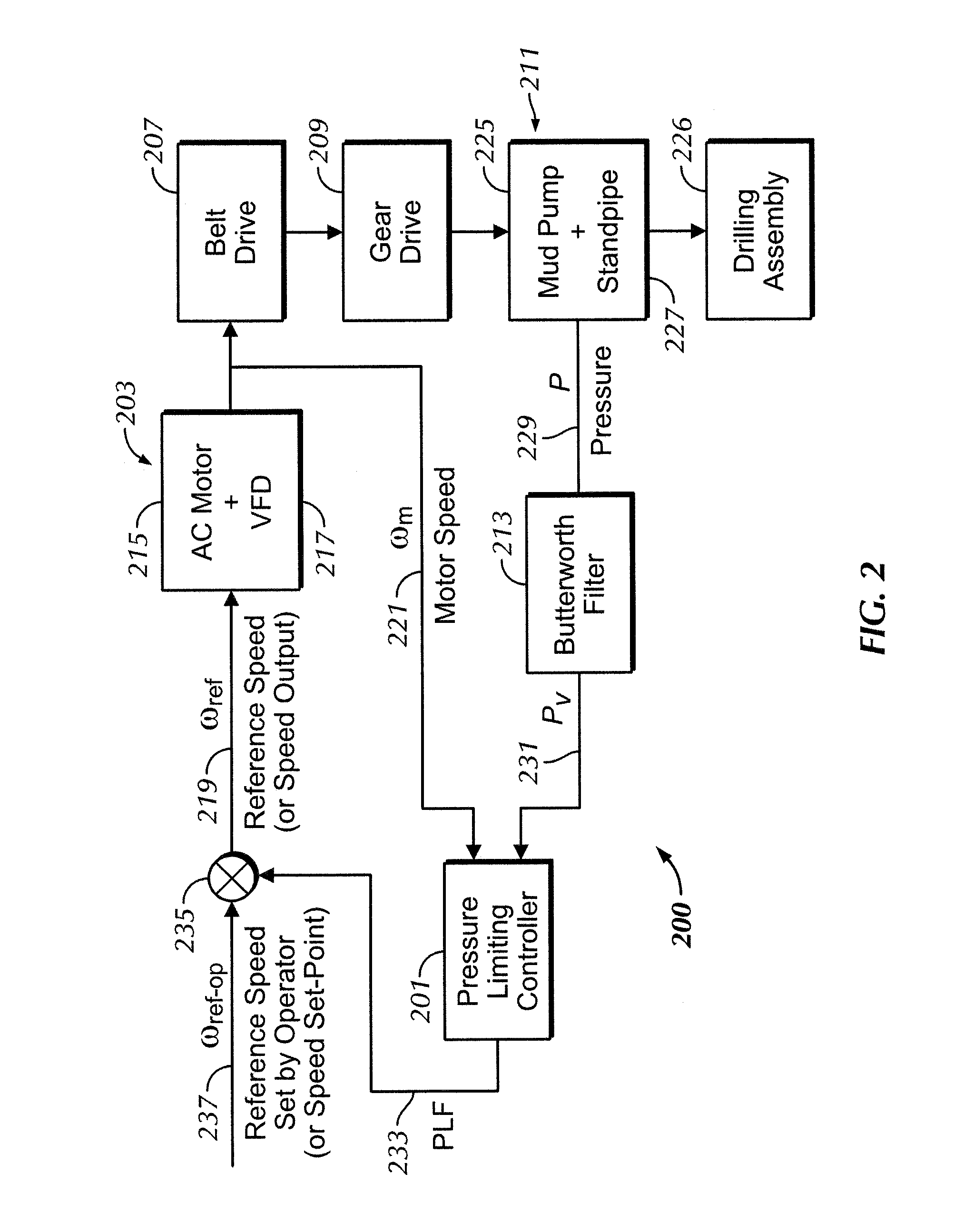
[0007]In general, in one aspect, embodiments disclosed herein relate to a mud pump system comprising: a pump adapted to pump a pressurized flow of mud from a mud container through a drillstring in a borehole; pressure sensors disposed in contact with the pressurized flow for detecting a pressure of the pressurized flow; a pressure limiting controller configured to control a motor speed of the pump in response to the pressure detected by the pressure sensors, wherein the pressure limiting controller generates a pressure limiting factor output using a pressure feedback input and a motor speed input to calculate a fluid conductance estimate, wherein the pressure limiting controller maintains the pressure limiting factor output at a maximum value based on a pressure set-point, wherein the pressure limiting controller continuously updates a normal fluid conductance value based on the fluid conductance estimate while the pressure limiting factor output remains at the maximum value, wherein the pressure limiting controller freezes the normal fluid conductance value, if the pressure limiting factor output is less than the maximum value, wherein the pressure limiting controller calculates a change in fluid conductance based on the normal fluid conductance value and the fluid conductance estimate, wherein the pressure limiting controller generates at least one adaptive gain based on the change in fluid conductance, and wherein the pressure limiting controller controls a motor speed of a pump in the mud pump system based on the at least one adaptive gain.

Problems solved by technology

However, these hydraulic characteristics can suddenly change due to blockages in the drill bit.
If the pumping rate is maintained the same as before, these blockages can cause a sudden surge in mud pressure.
However, these safety valves present a limitation because when they open in response to a sudden pressure surge, the mud flow diverts back to the surface tanks, shutting down the drilling operation.
Frequent shutdowns are undesirable.
Furthermore, conventional pressure control systems are generally unstable and cannot accommodate various levels of blockage and operating conditions.

Method used


Image

  • Pressure limiting controller
  • Pressure limiting controller
  • Pressure limiting controller

Examples


Embodiment Construction

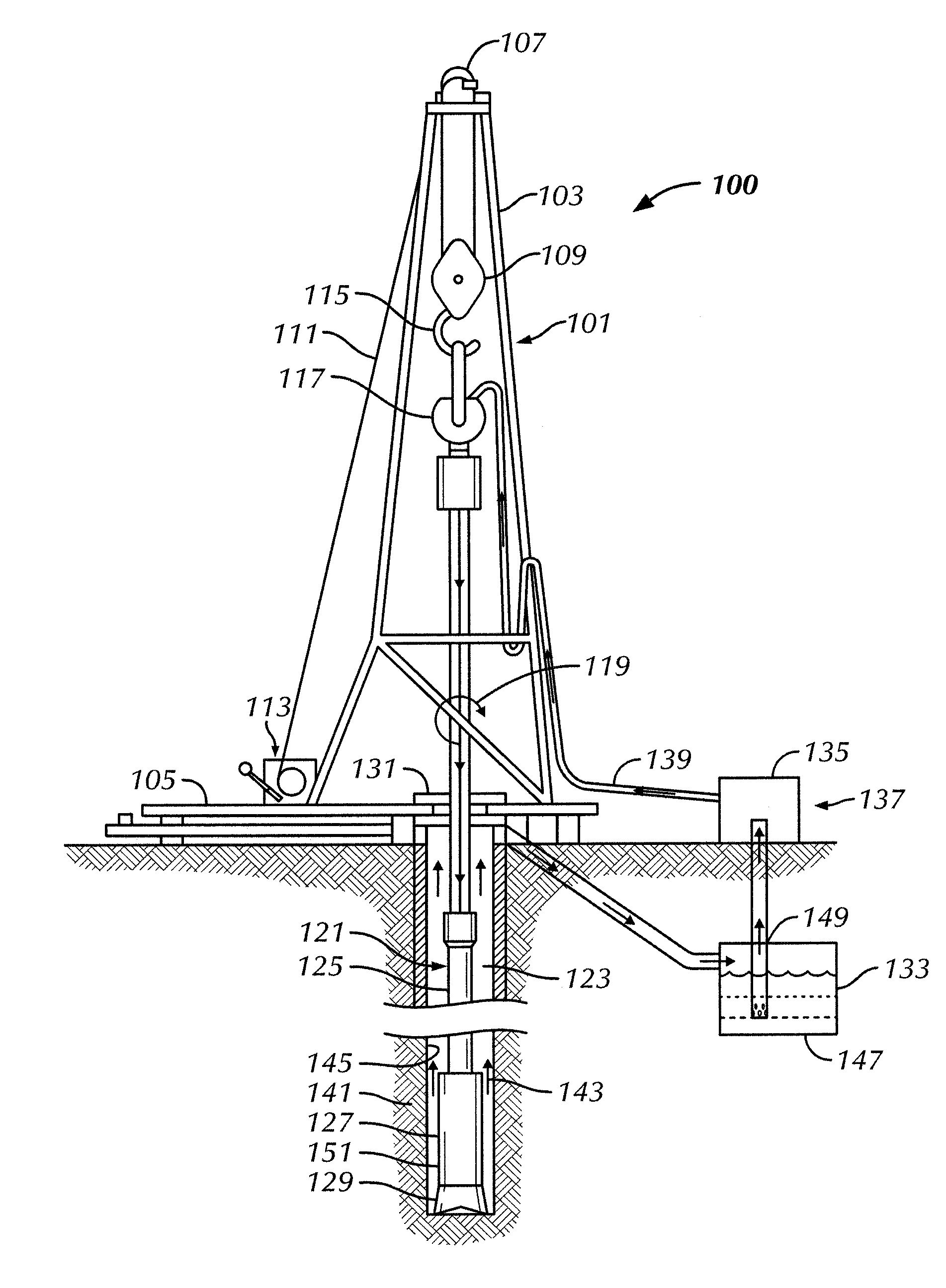
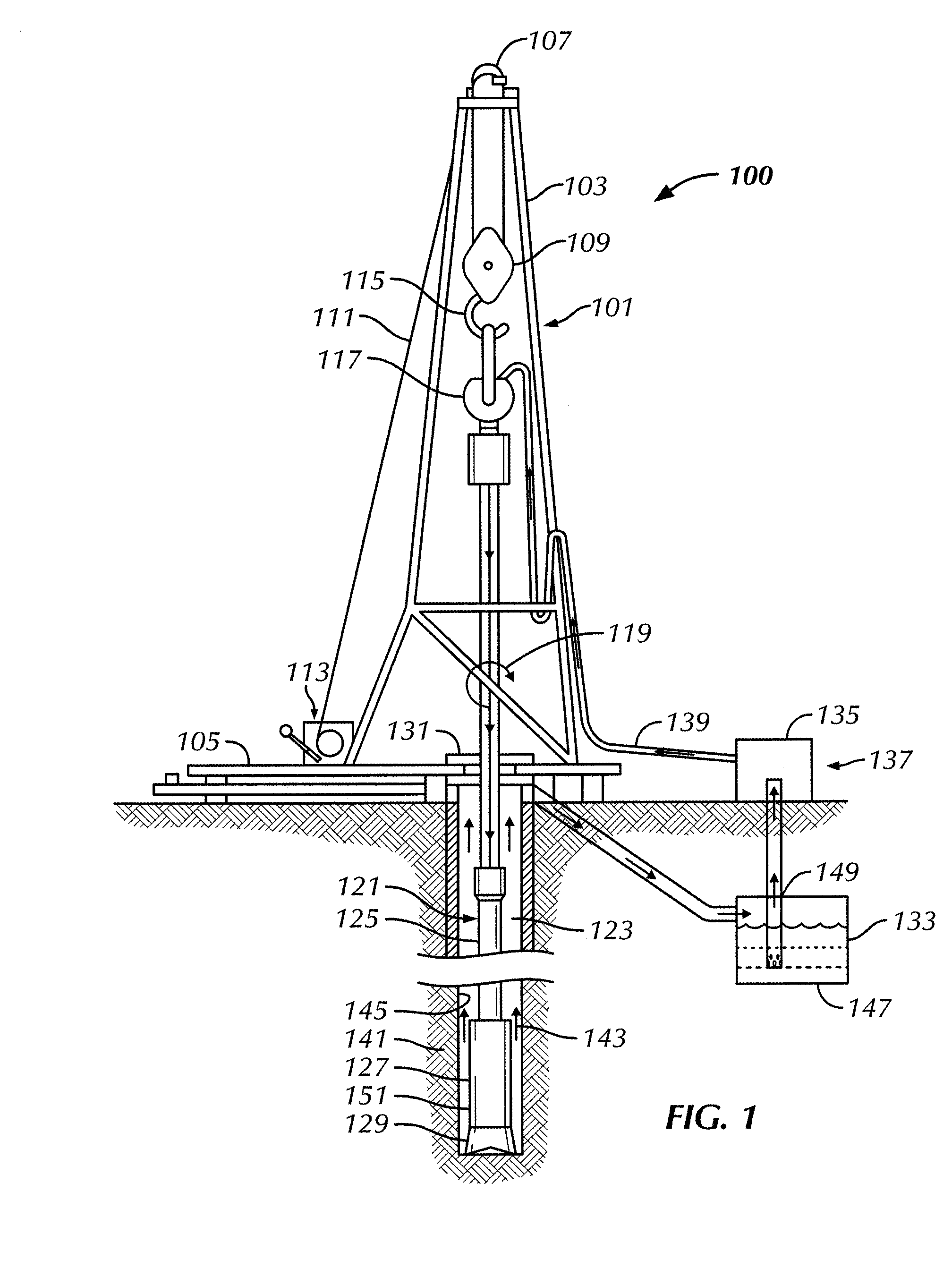
[0018]Embodiments of the present invention will be described below with reference to the figures. In one aspect, embodiments disclosed herein relate to apparatus and methods for controlling drilling fluid or “mud” pressure in a mud pump system. More specifically, embodiments disclosed herein relate to using a pressure limiting controller to control mud pressure in a drilling rig.

[0019]Referring initially to FIG. 1, a rotary drilling system 100 including a drilling rig 101 is shown. While drilling rig 101 is depicted in FIG. 1 as a land-based rig, it should be understood by one of ordinary skill in the art that embodiments of the present disclosure may apply to any drilling system including, but not limited to, offshore drilling rigs such as jack-up rigs, semi-submersible rigs, drill ships, and the like. Additionally, although drilling rig 101 is shown as a conventional rotary rig, wherein drillstring rotation is performed by a rotary table, those skilled in the art in possession of ...


PUM


Abstract

A method of controlling pressure in a mud pump system includes generating a pressure limiting factor output using a pressure feedback input and a motor speed input to calculate a fluid conductance estimate, maintaining the pressure limiting factor output at a maximum value based on a pressure set-point, continuously updating a normal fluid conductance value based on the fluid conductance estimate while the pressure limiting factor output remains at the maximum value, freezing the normal fluid conductance value, if the pressure limiting factor output is less than the maximum value, calculating a change in fluid conductance based on the normal fluid conductance value and the fluid conductance estimate, generating at least one adaptive gain based on the change in fluid conductance, and controlling a motor speed of a pump in the mud pump system based on the at least one adaptive gain.

Description

BACKGROUND OF INVENTION[0001]1. Field of the Invention[0002]Embodiments disclosed herein relate generally to apparatus and methods for controlling drilling fluid or “mud” pressure in a mud pump system. More specifically, embodiments disclosed herein relate to using a pressure limiting controller for controlling mud pressure.[0003]2. Background Art[0004]During a drilling operation, drilling fluid or “mud” is circulated through a mud pump system. Typically, mud flows down a drillstring to a rotating drill bit, which is suspended in a borehole. The mud flows through the drill bit by exiting through openings in the drill bit. As the mud exits, it flushes out drill cuttings generated by the drill bit. Then, the mud flows up an annular space between the drillstring and the sides of the borehole, carrying the drill cuttings to the surface.[0005]Under normal operating conditions of the mud pump system, the factors affecting the hydraulic characteristics of the mud are fairly constant at a g...

Claims


Application Information

Patent Timeline
Patent Type & Authority Applications(United States)
IPC IPC(8): E21B21/08
CPCE21B21/08
Inventor HOPWOOD, FERGUSNATARAJAN, ARUN
Owner SCHLUMBERGER TECH CORP
Learn More