Inductively Coupled Radio Frequency Identification (RFID) Transponder

a radio frequency identification and transponder technology, applied in the field of radio frequency identification (rfid) transponders, can solve the problems of introduction of a ferrite core, no longer available for supplying rfid transponders, and undesirable attenuation, etc., to achieve mechanical robustness, reduce the structural size of rfid transponders, and reduce the cost of manufacturing. simple and flexible

Inactive Publication Date: 2012-03-01
SIEMENS AG
View PDF2 Cites 3 Cited by
  • Summary
  • Abstract
  • Description
  • Claims
  • Application Information

AI Technical Summary

Benefits of technology

[0009]It is therefore an object of the present invention to provide an alternative to the ferrite cores used in a radio frequency identification (RFID) t...

Problems solved by technology

However, this is problematic in cases in which the RFID transponder is operated on a metallic surface or in a depression in a metallic workpiece.
In these cases, often a large portion of the magnetic flux is conducted through the metallic workpiece and laterally past the transmitting and receiving coil (or simply coil), where the energy of the alternating magnetic field is largely converted into heat by eddy current losses and is therefore no longer available for supplying the RFID transponder.
Conversely, the emissions of the RFID transponder in the case of an arrangement on a metallic workpiece are also allowed to be conducted directly into the metallic workpiece, such that an undesirable atten...

Method used


Image

  • Inductively Coupled Radio Frequency Identification (RFID) Transponder
  • Inductively Coupled Radio Frequency Identification (RFID) Transponder

Examples


Embodiment Construction

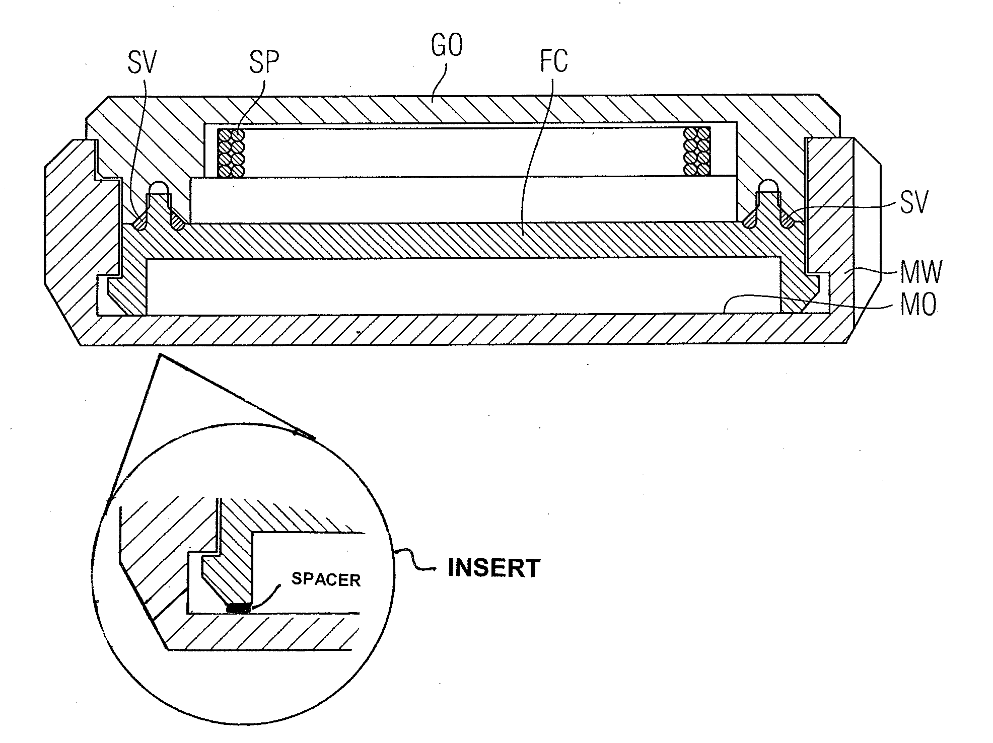
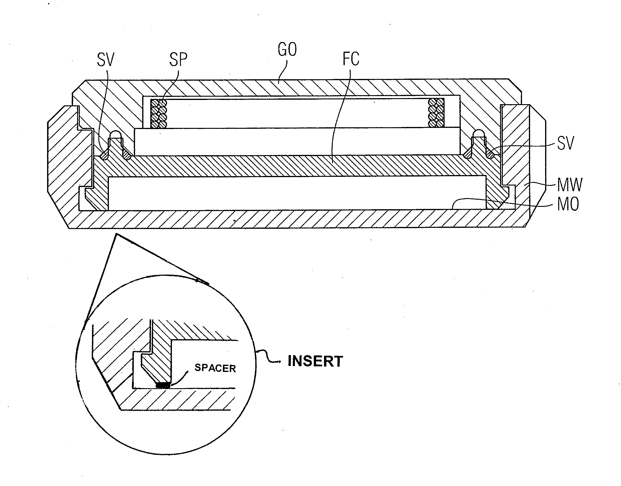
[0019]The FIGURE is a cross-sectional view illustrating a metallic workpiece MW composed of a ferromagnetic material having a metallic surface MO. Here, the metallic workpiece MW is only illustrated partially, that is to say in a region having a depression for receiving an RFID transponder. Instead of the configuration of a depression for receiving or for latching in an RFID transponder, it is also possible to consider smooth surfaces of metallic workpieces MW, onto which RFID transponders can be adhesively bonded, screwed or fixed in some other way. The RFID transponder has operating electronics (not illustrated here in detail) connected to a transmitting and receiving coil SP. The sectional illustration illustrates only a few windings of the coil SP by way of example. Although the RFID transponder shown here is constructed substantially in a circular manner, i.e., in a rotationally symmetrical manner, in a plan view the coil SP can, for example, also be shaped in a rectangular fas...


PUM


Abstract

An RFID transponder comprising a housing for mounting on or in a workpiece having a metallic surface, where the RFID transponder is provided for inductive coupling to an RFID reader, where that side of the RFID transponder which is to face the metallic surface is provided with a ferrite component for guiding the magnetic flux from and to a side of the RFID transponder which is to face away from the metallic surface, and where the ferrite component comprises a composite material composed of a first plastic and ferrite powder and forms a first part of the housing, which is to face the metallic surface. Such an RFID transponder is small and robust and additionally simple to produce.

Description

BACKGROUND OF THE INVENTION[0001]1. Field of the Invention[0002]The invention relates to Radio Frequency Identification (RFID) Transponders and, more particularly, to an RFID transponder comprising a housing for mounting on or in a workpiece having a metallic surface.[0003]2. Description of the Related Art[0004]Mobile data memories that can be read contactessly are often used for identifying goods, machines and other articles. Here, optically readable barcode labels are increasingly being replaced by electromagnetically or magnetically writeable and readable radiofrequency identification (RFID) labels, i.e., RFID transponders. In preferred configurations, these RFID transponders operate without a dedicated power supply, such as a battery.[0005]Different technologies are used in RFID transponders depending on the case of use. Thus, for labeling garments and other far field applications, for example, the RFID transponders are coupled to the reader by radio, i.e., by electromagnetic wa...

Claims


Application Information

Patent Timeline
IPC IPC(8): G06K19/077
CPCG06K19/07771G06K19/07749
Inventor KUBE, ROLANDSTADELMANN, BERND
Owner SIEMENS AG
Why Eureka
Try Eureka