Vertical axis wind turbine generator

a technology of wind turbine generator and vertical axis, which is applied in the direction of electric generator control, renewable energy generation, greenhouse gas reduction, etc., can solve the problem that the vertical axis wind turbine generator cannot stabilize the behavior of its own blade, and achieve the effect of easy deformation

Inactive Publication Date: 2012-03-01
KIKUCHI NAOMI
View PDF3 Cites 21 Cited by
  • Summary
  • Abstract
  • Description
  • Claims
  • Application Information

AI Technical Summary

Benefits of technology

[0011]With the view of the foregoing problem to be solved, it is an object of the present invention to make it possible to stabilize the behavior of a blade according to wind power with simple structure in a vertical axis wind turbine generator provided with a blade so that a rotating shaft becomes perpendicular to a wind direction.
[0014]According to the first aspect of the present invention, an opened or closed state of the blade plate subjected to wind pressure can be regulated by the elastic force of the spring. Hence, the behavior of the blade can be stabilized according to a wind force with a simple structure.
[0015]According to the second aspect of the present invention, the blade plate is formed from the spring plate material and hence can easily deform according to a wind direction.

Problems solved by technology

Conventionally, however, there has been no vertical axis wind turbine generator capable of stabilizing the behavior of its own blade according to a wind power, using a simple structure.

Method used


Image

  • Vertical axis wind turbine generator
  • Vertical axis wind turbine generator
  • Vertical axis wind turbine generator

Examples


embodiment 2

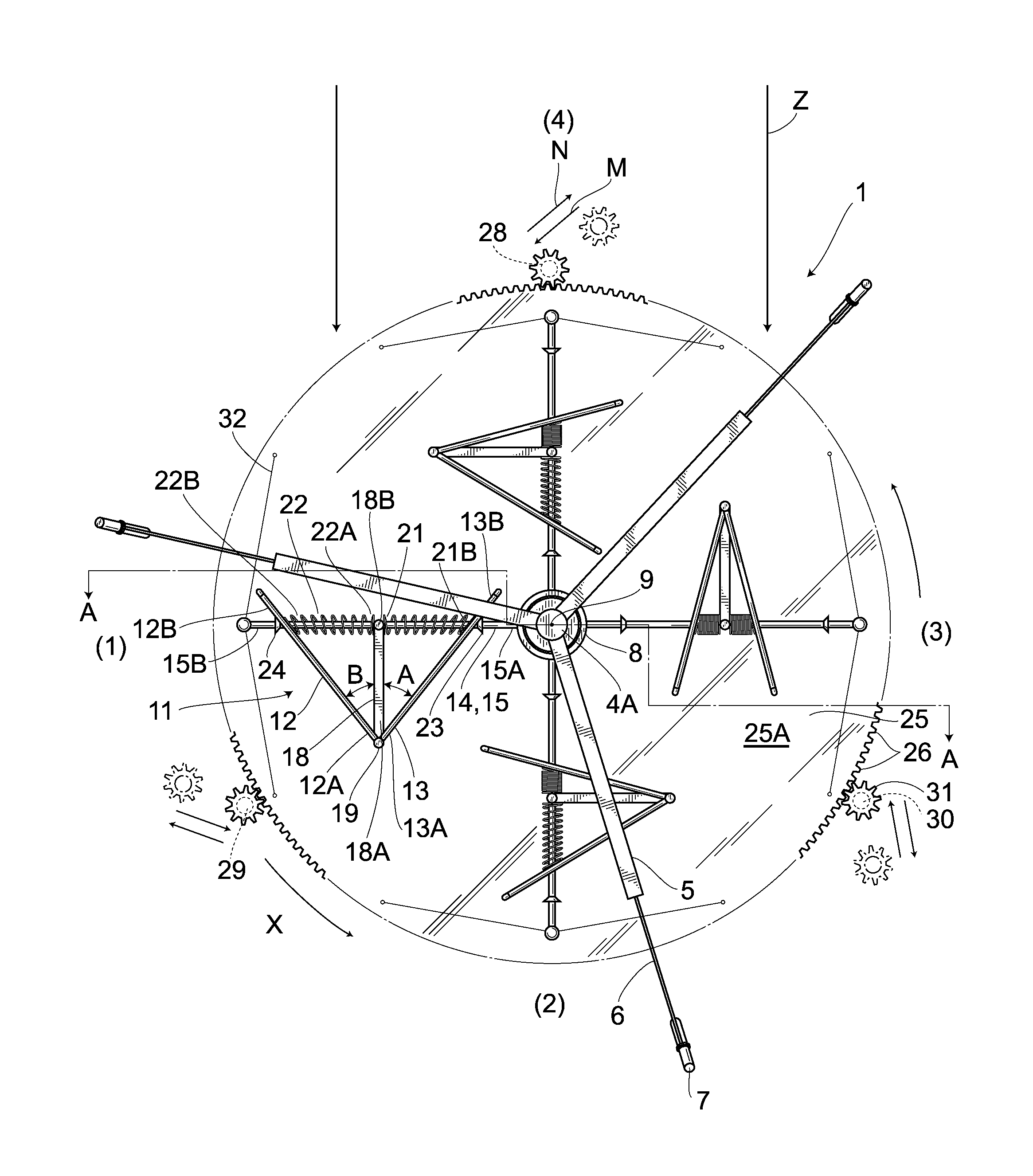
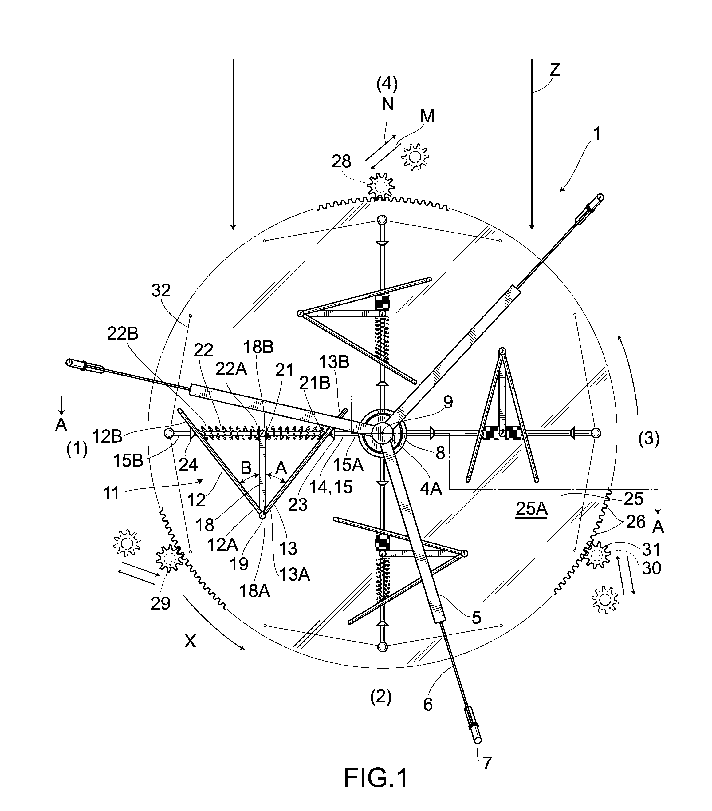
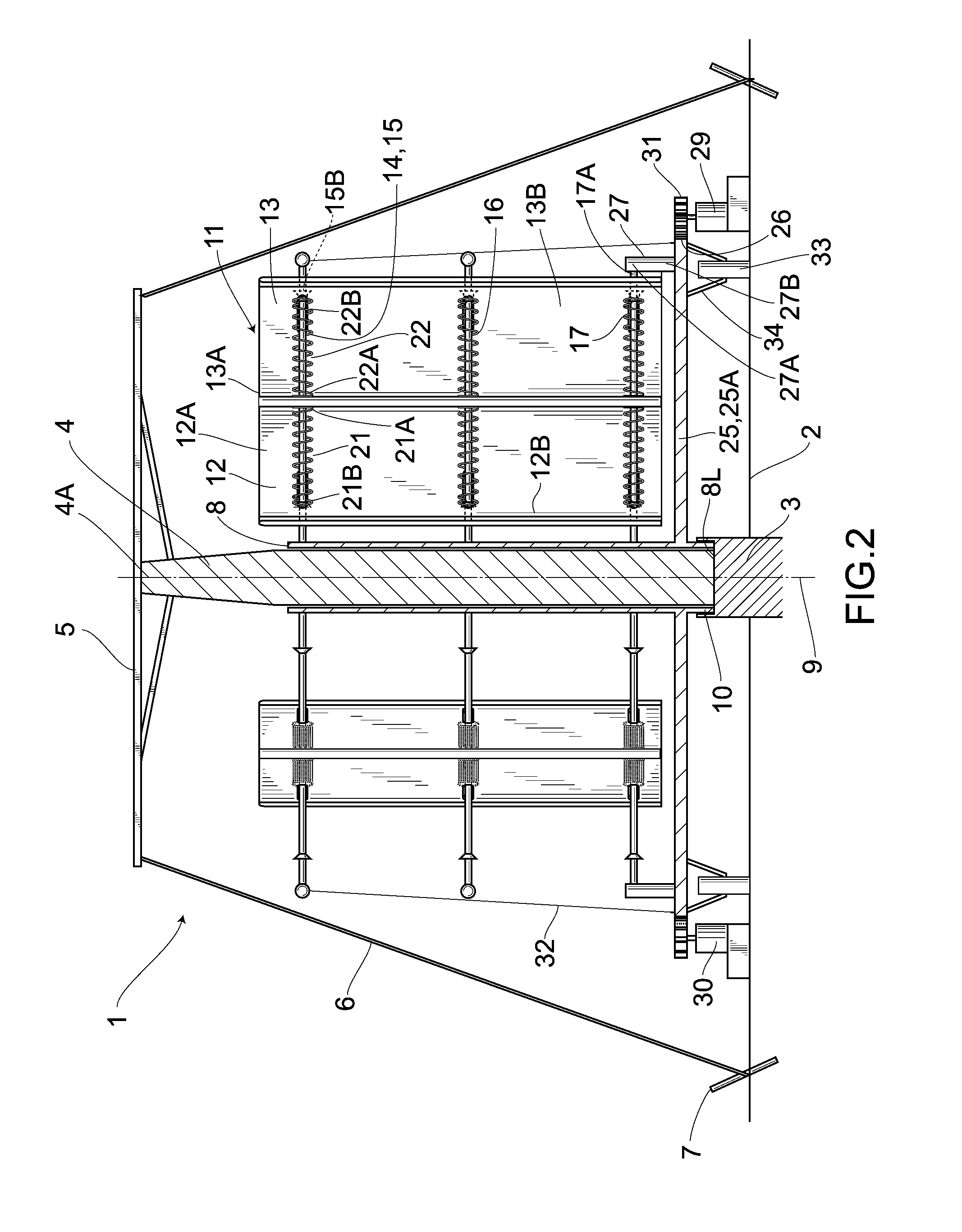
[0059]Hereunder is a description of a different embodiment. In addition, the same numeral symbols are used for parts the same as in the foregoing embodiment and the detailed description thereof is omitted.

[0060]FIG. 8 shows the embodiment 2. In the embodiment 2, a first rotating shaft 8′ stands at the center of a rotating plate 61 that is rectangular in plane and is fixed to an upper surface of a speed increasing disc gear 25′. An intermediary portion in the longitudinal direction of a first arm 14′ provided radially from the first rotating shaft 8′ is provided in a circular-arch shaped manner so as to recede to a reverse direction to one rotating direction X′. The proximal portions 12′B, 13′B of divided blade plates 12′, 13′ are slidably provided on the first arm 14′. One end 21′A of a coil spring 21′ wound around the first arm 14′ is coupled to the divided blade plate 12′, while the other end 21′B is coupled to the divided blade plate 13′. Front edges 12′A, 13′A of the right-and-l...

embodiment 3

[0066]FIGS. 9 to 11 show an embodiment 3. The generator according to the embodiment 3 eliminates the support member 18 employed in the embodiment 1 to pivotally couple the front edges 12A, 13A of the divided blade plates 12, 13 only via the turnable coupling means 19. Then, one end 21″A and the other end 21″B of the coil spring 21″ wound around the arm 15 are coupled to the divided blade plates 12, 13, respectively.

[0067]Accordingly, as is the case with the embodiment 1, when wind in the wind direction Z blows from the windward side, the rear opening of the right-and-left pair of the divided blade plates 12, 13 comes to be opposed to the wind direction Z (a position indicated by (1) in FIG. 9), the inner surfaces of the right-and-left pair of the divided blade plates 12, 13 are subjected to the wind pressure and the divided blade plates 12, 13 is pressed by the wind pressure. As a result, the torque generated in the right-and-left pair of the divided blade plates 12, 13 is transmitt...

embodiment 4

[0070]FIG. 12 shows a fourth embodiment. As with the third embodiment, with the support member 18 eliminated, the front edges 12″A, 13″A of the divided blade plates 12″, 13″ are coupled only via the turnable coupling means 19 and one end 21″ A and the other end 21″ B of a coil spring 21″ wound around the arm 15 are linked to the divided blade plates 13″, 12″, respectively.

[0071]Then, the first and second divided blade plates 12″, 13″ are formed from a spring plate material made of spring steel. A symbol 12″K indicates a penetrated portion which is formed in the upper portion of the first divided blade plates 12″ and is used for the first arm 14 (first upper arm 15). This penetrated portion is formed horizontally long from a front edge 12A″ to a proximal end 12″B and therefore in planar view, the first and second divided blade plates 12″, 13″ are allowed to slide, in relation to the first arm 25, perpendicularly to the longitudinal direction of the first upper arm 15. Besides, a symb...


PUM


Abstract

A vertical axis wind turbine generator whose blade is allowed to stably operate according to a win force, with a simple structure. The generator is equipped with an arm whose proximal end is coupled to a rotating shaft and whose front edge is provided laterally to a rotating central axis line, and a blade mounted on the arm. A pair of divided blade plates is arranged in a V-shaped form. One sides of the blades are pivotally coupled together, while the opposite sides are provided in openable and closable manner. Coil springs are interposed between the blade plates and the arm. The blade plates are allowed to open or close according to wind directions and wind pressures, so that the rotation speed is regulated with a simple structure, enabling stable electric power generation.

Description

CROSS REFERENCE TO RELATED APPLICATIONS[0001]This application claims the benefit of Japanese Patent Application No. 2010-191446, filed Aug. 27, 2010, and Japanese Patent Application No. 2011-167721, filed Jul. 29, 2011, both of which are herein incorporated by reference in their entireties.BACKGROUND OF THE INVENTION[0002]1. Field of the Invention[0003]The present invention relates to a vertical axis wind turbine generator.[0004]2. Description of the Related Art[0005]Heretofore, there has been known a horizontal axis wind turbine generator, as shown in FIG. 14 and FIG. 15. In this horizontal axis wind turbine generator employing the conventional technique, a blade 102 is provided on the windward side of a rotating shaft 101 horizontally arranged, while a generator 103 is provided on the leeward side of the rotating shaft 101.[0006]As this kind of horizontal axis wind turbine generator, there is publicly known a wind power generator in which a horizontal axis wind turbine generator i...

Claims


Application Information

Patent Timeline
Patent Type & Authority Applications(United States)
IPC IPC(8): F03D9/00
CPCF03D3/067F03D7/0224F03D11/02Y02E10/74F05B2260/71F05B2260/74F05B2260/75F05B2260/4031F03D15/00F03D9/25F03D15/10
Inventor KIKUCHI, NAOMI
Owner KIKUCHI NAOMI
Why Eureka
Try Eureka