

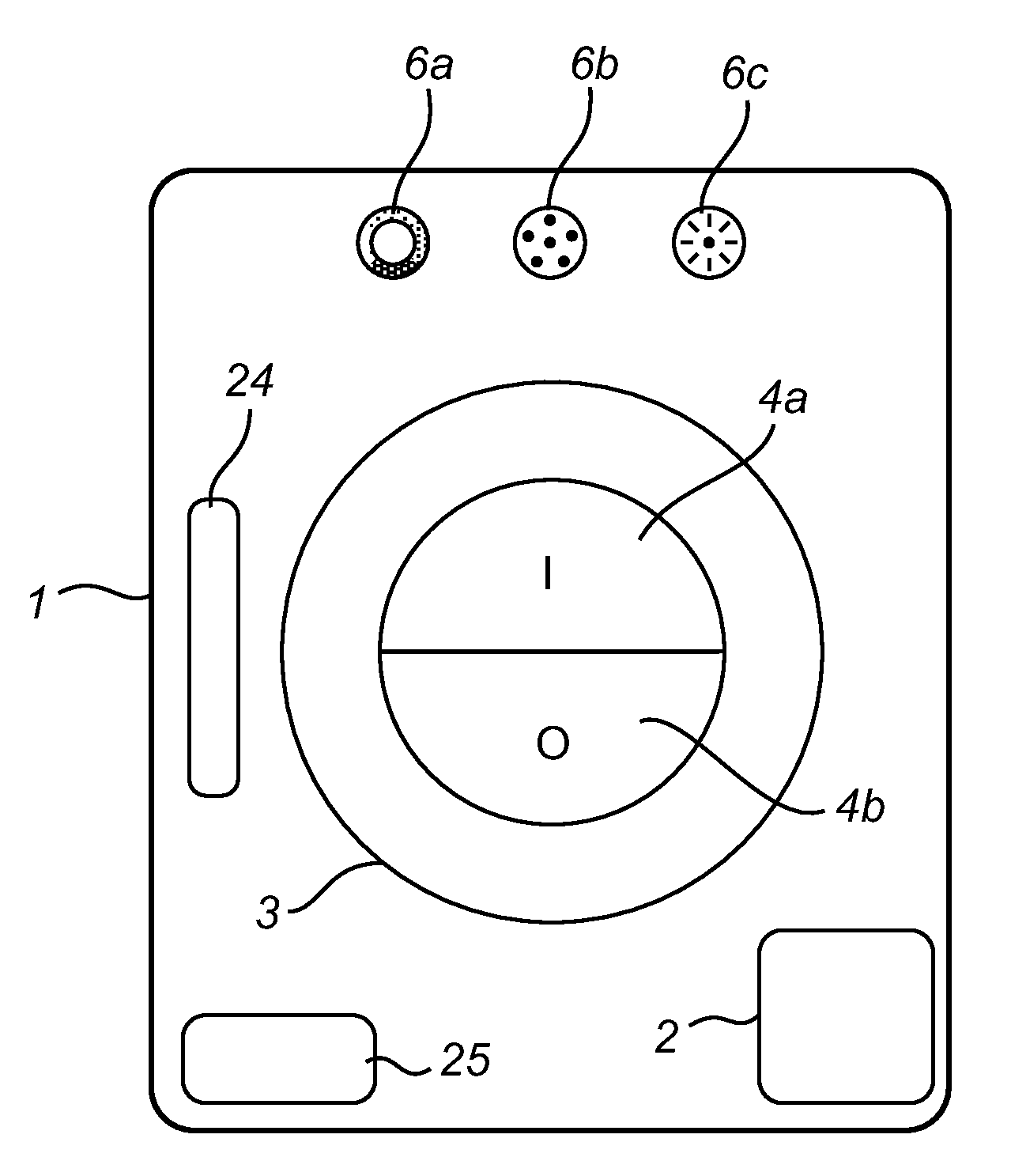
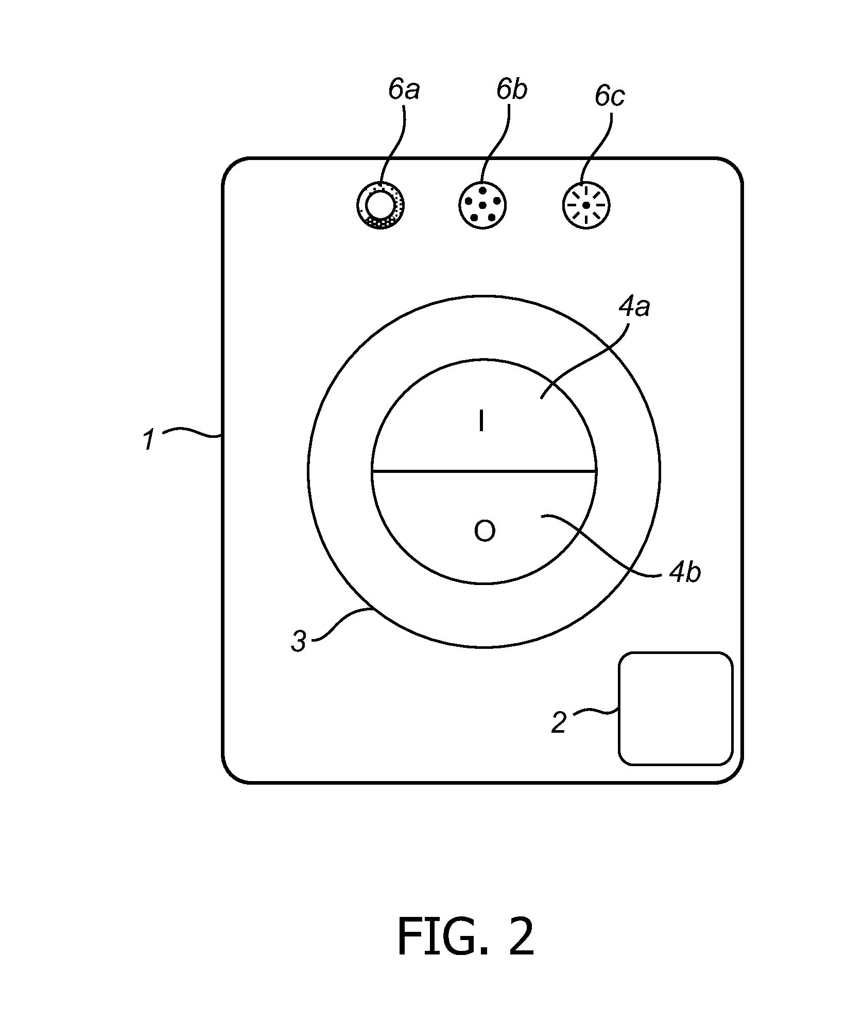
User interface with circular light guided ring with adaptive appearance depending on function
a user interface and function technology, applied in the direction of process and machine control, instruments, pulse techniques, etc., can solve the problems of inability to understand the user, difficulty in providing indications to the user, and general complexity of prior art devices, so as to facilitate the provision of indications and facilitate the user's us
- Summary
- Abstract
- Description
- Claims
- Application Information
AI Technical Summary
Benefits of technology
Problems solved by technology
Method used
Image

Examples
Embodiment Construction
[0060]The following is a description of exemplifying embodiments in accordance with the present invention. It is to be understood that the following description is non-limiting and for the purpose of describing the principles of the invention.
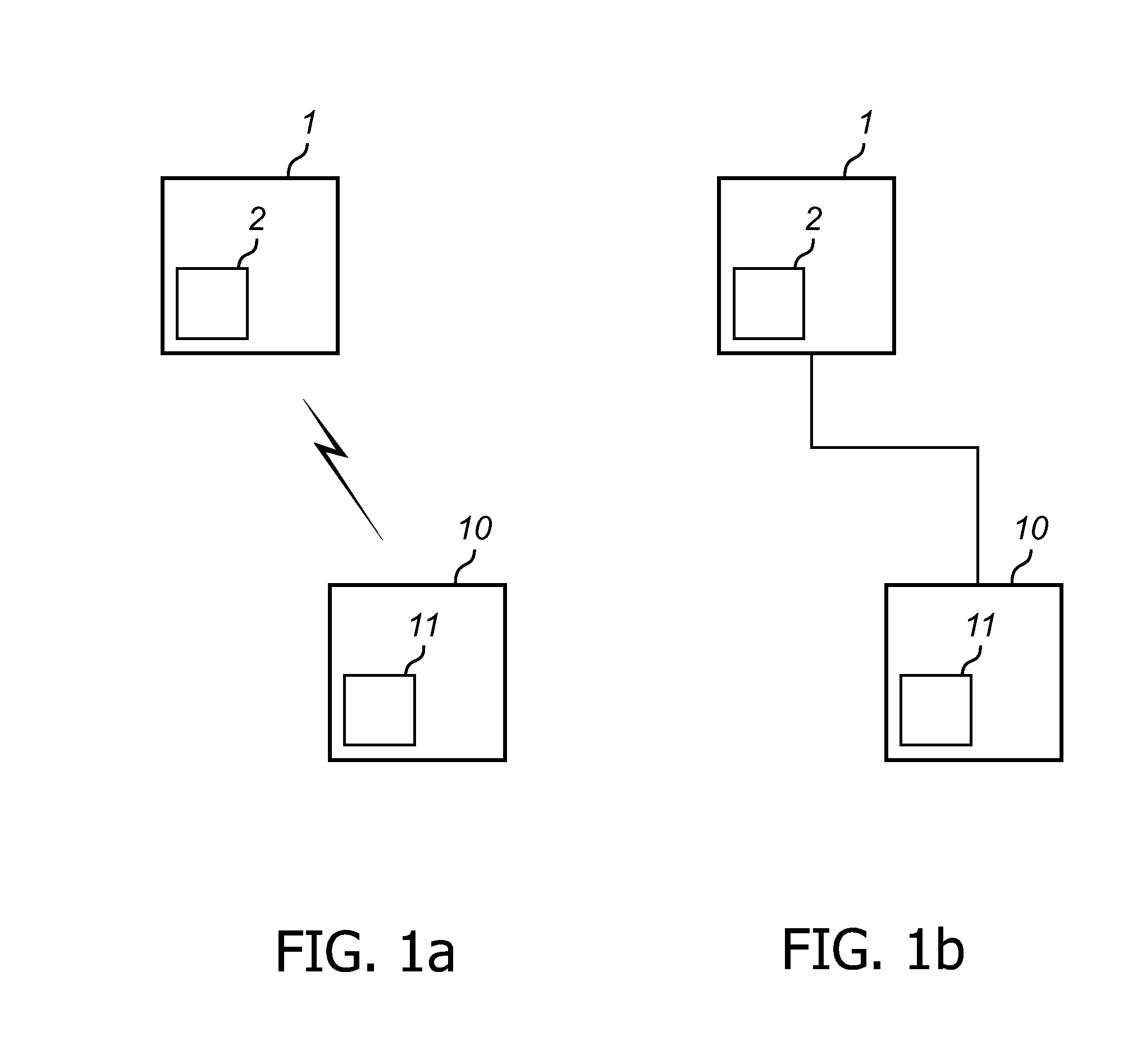
[0061]Referring to FIG. 1A, there is shown a schematic block diagram of a control device 1 according to an exemplifying embodiment of the present invention. The control device 1 may comprise a communication unit 2 adapted to communicate control signals, corresponding to user input on the control device 1, via wireless communications to a light source 10. The light source 10 may in turn comprise a communication unit 11 adapted to receive control signals communicated from the communication unit 2 of the control device 1, on the basis of which control signals properties of light emitted from the light source 10 may be adjusted.
[0062]Referring now to FIG. 1B, there is shown a schematic block diagram of a control device 1 according to another exempl...
PUM
 Abstract
Description
Claims
Application Information