Programmable tire monitoring device and its method of use

a tire pressure monitoring and programmable technology, applied in tire measurement, vehicle components, transportation and packaging, etc., can solve the problems of not allowing the commercial wireless or programmable tire pressure monitoring device to fit all commercial cars, complicating further maintenance work and inventory control, and not satisfying the function of commercial tire monitoring devices. , to achieve the effect of high accuracy and reliability, and convenient us

Inactive Publication Date: 2012-03-01
CUB ELECPARTS
View PDF22 Cites 26 Cited by
  • Summary
  • Abstract
  • Description
  • Claims
  • Application Information

AI Technical Summary

Benefits of technology

[0006]The present invention has been accomplished under the circumstances in view. It is the main object of the present invention to provide a programmable tire monitoring device and its method of use, which has the advantages of easy of use and high accuracy and reliability.

Problems solved by technology

However, commercial tire monitoring devices are still not satisfactory in function.
This limitation complicates further maintenance work and inventory control.
However, the limited storage space of the memory and the processing ability of the processor do not allow these commercial wireless or programmable tire-pressure monitoring devices to fit all commercial cars.
Further, when programming in a wireless manner, the transmission of wireless data is not directional, i.e., the signal cannot be exclusively sent to the tire-pressure monitoring device in one specific tire of a car.
However, these tire-pressure monitoring devices do not allow the user to switch on / off the battery set freely, and therefore the battery set keeps supplying electric power either the tire-pressure monitoring device is in work or not in work, causing possible power loss, leakage of battery fluid or battery corrosion.
However, commercial tire-pressure monitoring devices cannot meet this requirement.

Method used


Image

  • Programmable tire monitoring device and its method of use
  • Programmable tire monitoring device and its method of use
  • Programmable tire monitoring device and its method of use

Examples


Embodiment Construction

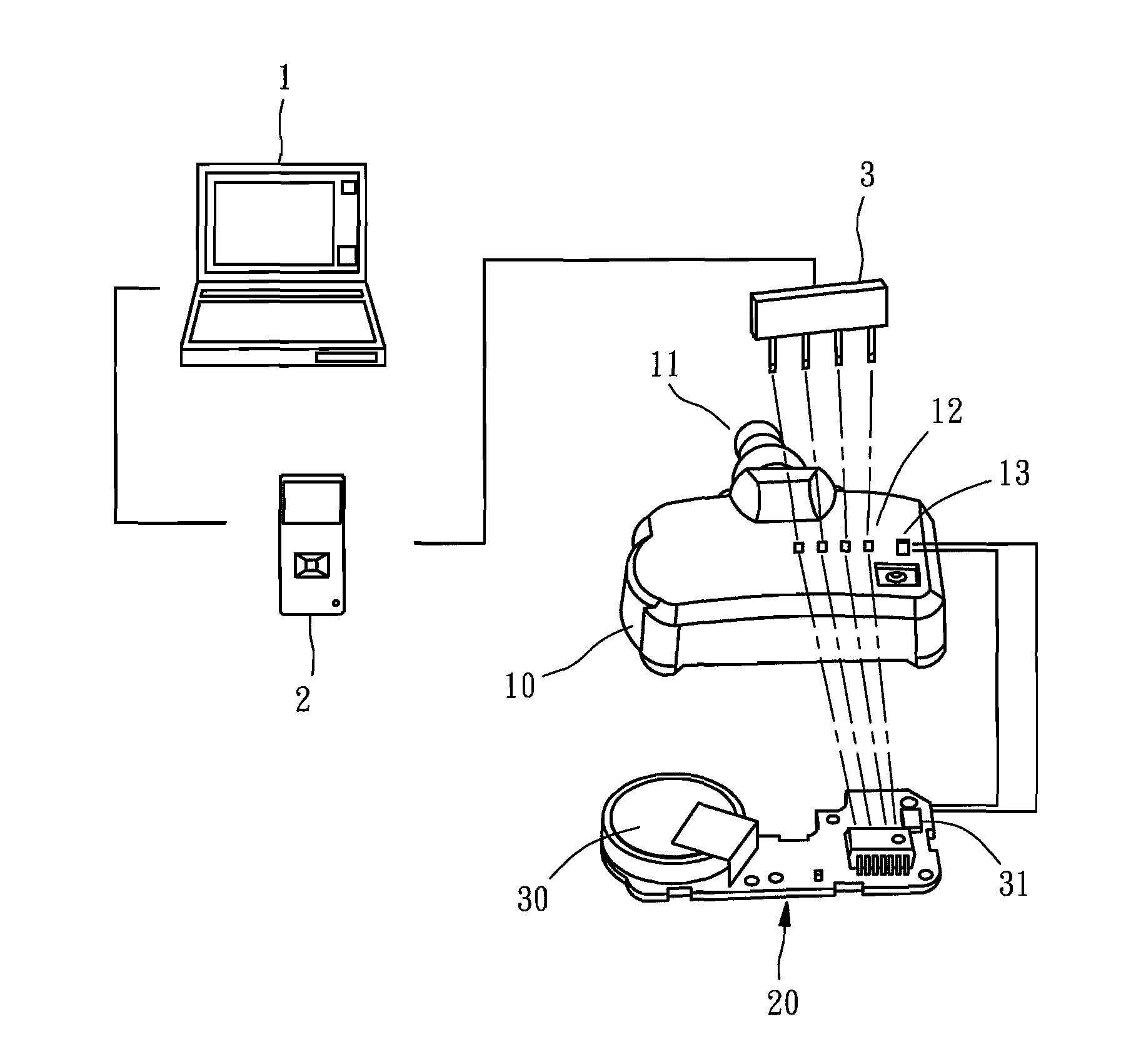
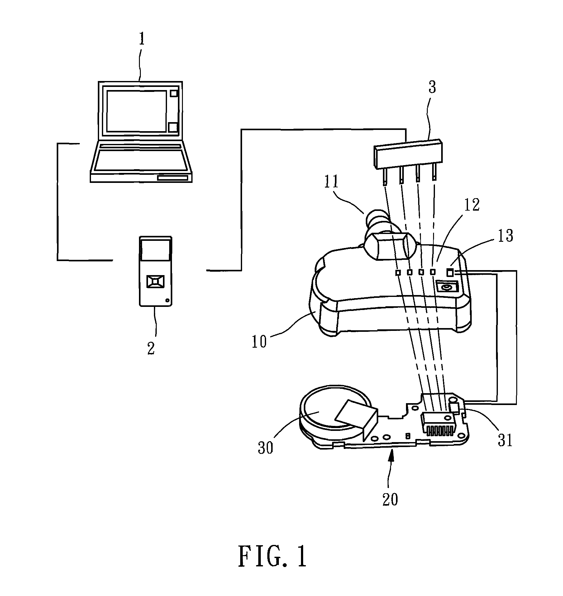
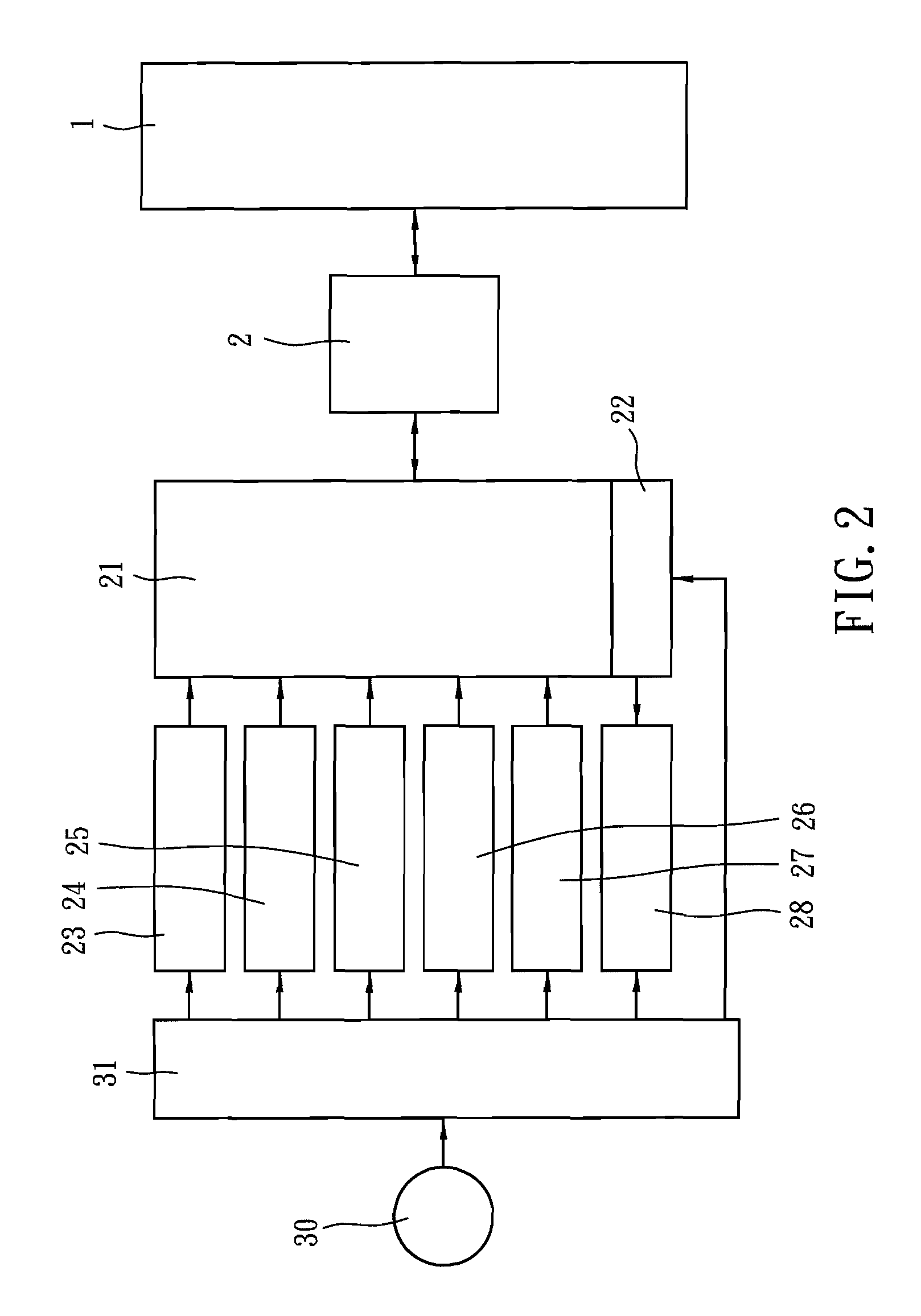
[0011]Referring to FIGS. 1 and 2, a programmable tire monitoring device in accordance with the present invention is shown for use in a car, comprising a casing 10, which has an air nozzle 11 located on one end thereof and a set of pin-connection holes 12 and a switch hole 13 located on the top side thereof, a circuit board 20 mounted inside the casing 10 and carrying a processor 21 and a memory 22 that is an electrically erasable programmable read / write memory, a pressure sensor 23 electrically connected to the processor 21 and adapted for sensing the internal pressure of one tire of the car, a temperature sensor 24 electrically connected to the processor 21 and adapted for sensing the internal temperature of the same tire, an acceleration sensor 25 electrically connected to the processor 21 and adapted for sensing the acceleration of the tire, a LF (Low Frequency) transmission interface 27 and a RF (Radio Frequency) transmission interface 28 respectively electrically connected to t...


PUM


Abstract

A programmable tire monitoring device includes a casing having an air nozzle on its one end and a set of pin-connection holes and a switch hole on its top side, a circuit board mounted in the casing and carrying a processor and a memory, a pressure sensor and a temperature sensor and an acceleration sensor electrically connected to the processor for sensing the pressure, temperature and acceleration of one tire of a car, a transmission interface for transmitting the measured data to a receiver in the car, a connection port installed in the circuit board corresponding to the pin-connection holes for enabling the circuit board to be connected with an external electrical connector, a battery set for providing the programmable tire monitoring device with the necessary electric power, a voltage sensor electrically connected to the processor for sensing the voltage of the battery set, and a power switch for switching on/off the circuit of the battery set. The invention relates also to the method of using the programmable tire monitoring device.

Description

BACKGROUND OF THE INVENTION[0001]1. Field of the Invention[0002]The present invention relates to tire pressure measuring technology and more particularly, to a programmable tire monitoring device and its method of use.[0003]2. Description of the Related Art[0004]The tires of many commercial cars have a respective tire monitoring device installed therein to measure the tire temperature and the tire pressure and to provide the measured data to the driver for reference, enhancing driving safety. However, commercial tire monitoring devices are still not satisfactory in function. Because every supplier provides a specific coding method, these commercial tire monitoring devices have the characteristics of unique and specificity, i.e., one model of product simply fit the cars from one manufacturer or the cars of one or two models. This limitation complicates further maintenance work and inventory control.[0005]There are commercial wireless or programmable tire-pressure monitoring devices t...

Claims


Application Information

Patent Timeline
Patent Type & Authority Applications(United States)
IPC IPC(8): B60C23/02
CPCB60C23/041B60C23/0494B60C23/0479B60C23/0471
Inventor YU, SAN-CHUANHUNG, YUAN-TUNGHU, CHAO-CHING
Owner CUB ELECPARTS
Why Eureka
Try Eureka