Switchable Viewing Angle Display

a technology of rotating viewing angle and display, applied in the field of electronic displays, can solve the problems of reducing image quality, poor display power efficiency, and particularly critical waste of energy, and achieve the effects of reducing backlight intensities, reducing waste of energy, and prolonging the life of the battery of the display devi

Inactive Publication Date: 2012-03-01
SHARP KK
View PDF5 Cites 29 Cited by
  • Summary
  • Abstract
  • Description
  • Claims
  • Application Information

AI Technical Summary

Problems solved by technology

However, these films degrade the image quality by placing extra film layers over the LC front panel, and such a display has a limited number of applications.
However, this method does not limit the backlight spreading angles, so that light emitted outside the narrow viewing angle is wasted, leading to poor display power efficiencies.
The waste of energy is particularly critical for hand-held devices with battery supplied power.

Method used


Image

  • Switchable Viewing Angle Display
  • Switchable Viewing Angle Display
  • Switchable Viewing Angle Display

Examples


Embodiment Construction

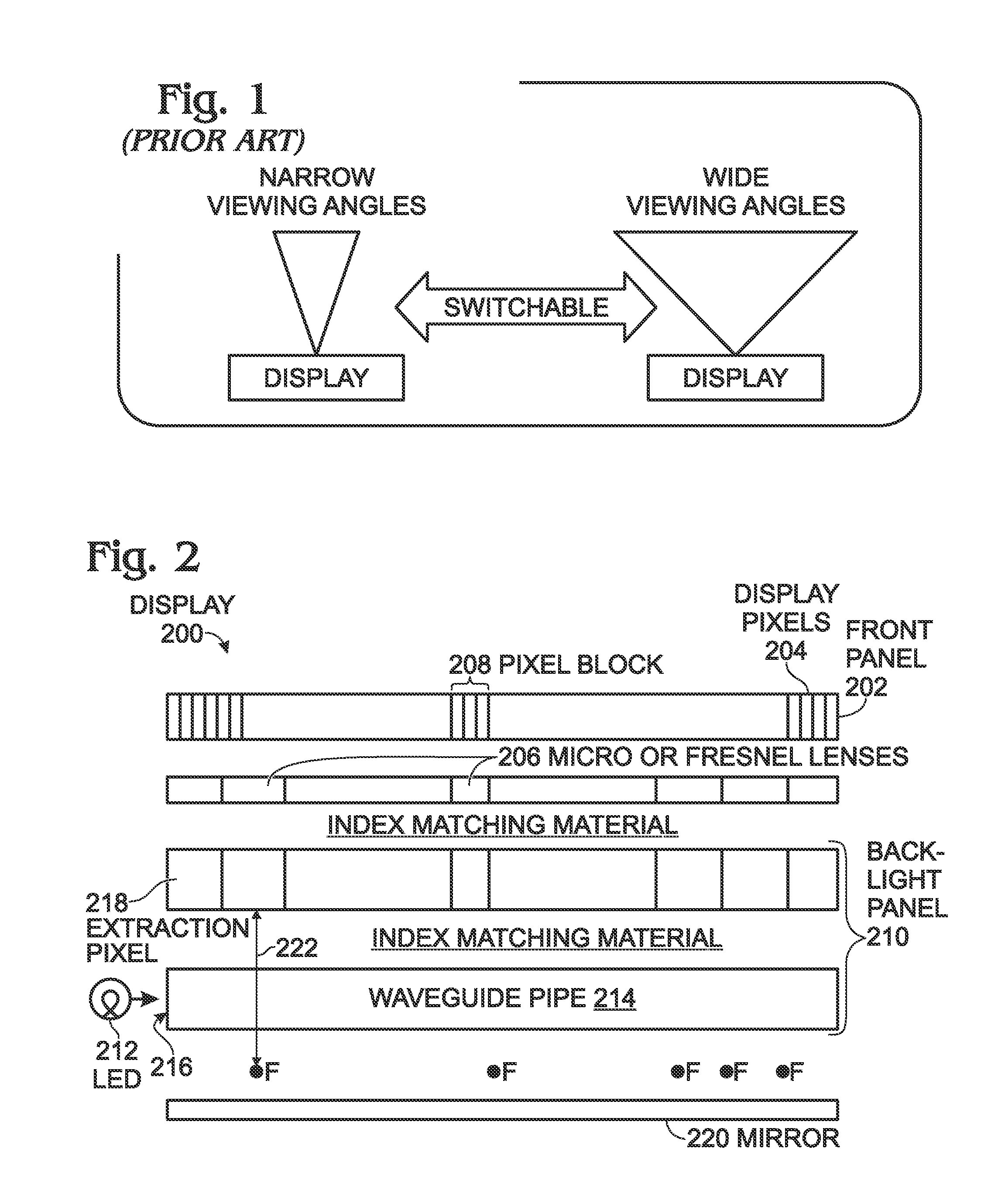
[0026]FIG. 2 is a schematic block diagram partial cross-sectional view depicting a switchable viewing angle display using arrayed microlenses and a waveguide pipe with selectable light extraction positions. The display 200 comprises a liquid crystal (LC) front panel 202 with an array of display pixels 204 arranged in a plurality of sequences. The display has application to any kind of display pixel requiring a backlight. In cross-section only a single sequence of display pixels 204 can be seen. An array of microlenses 206 underlies the array of display pixels 204, where each microlens 206 has a focal point (F) and each microlens 206 is associated with a corresponding block 208 of display pixel 204.

[0027]The backlight panel 10 includes a column of light emitting diodes (LEDs) 212. In cross-section only a single LED can be seen. An edge-coupled waveguide pipe 214 has an optical input 216 connected to the column of LEDs 212. An array of extraction pixels 218 is arranged in a plurality ...


PUM

PropertyMeasurementUnit
viewing anglesaaaaaaaaaa
distanceaaaaaaaaaa

Abstract

A switchable viewing angle display method is provided, using arrayed microlenses and a waveguide pipe with selectable light extraction positions. The method provides a front panel array of display pixels. Also provided is an array of microlenses underlying the array of display pixels. Each microlens has a focal point and each microlens is associated with a corresponding block of display pixels. A backlight panel has an edge-coupled waveguide pipe with an optical input connected to a column of light emitting diodes (LEDs). The backlight panel includes an array extraction pixels, each extraction pixel underlying a corresponding microlens, and the backlight panel also includes a planar mirror underlying the waveguide pipe. In response to a display viewing angle change command, a waveguide pipe's light extraction position selected, which is the distance between the extraction pixels and their corresponding microlenses, and the display viewing angle is changed.

Description

RELATED APPLICATION[0001]The application is a Continuation-in-Part of a pending application entitled, SCATTERING TUNABLE DISPLAY USING REFLECTIVE AND TRANSMISSIVE MODES OF ILLUMINATION, invented by Huang et al., Ser. No. 12 / 877,017, filed on Sep. 7, 2010, Attorney Docket No. SLA2750;[0002]which is a Continuation-in-Part of a pending application entitled, THREE-DIMENSIONAL DISPLAY USING ANGULAR PROJECTION BACKLIGHT, invented by Huang et al., Ser. No. 12 / 873,188, filed on Aug. 31, 2010, Attorney Docket No. SLA2739. Bother these applications are incorporated herein by reference.BACKGROUND OF THE INVENTION[0003]1. Field of the Invention[0004]This invention generally relates to electronic displays and, more particularly, to a display capable of selectively operating in wide and narrow display ranges.[0005]2. Description of the Related Art[0006]Large panel liquid crystal (LC) displays normally require large viewing angles, and designs have been significantly improved to expand the viewing...

Claims


Application Information

Patent Timeline
Patent Type & Authority Applications(United States)
IPC IPC(8): G09G3/36G02F1/1335G09G5/10
CPCG09G3/36G09G2320/0626G02F1/1323G09G3/342G09G2320/068
Inventor HUANG, JIANDONGVOUTSAS, APOSTOLOS T.
Owner SHARP KK
Why Eureka
Try Eureka