Total internal reflection energy/heat source

a technology of energy/heat source and total internal reflection, which is applied in the direction of instruments, optical elements, optical waveguide light guides, etc., can solve the problems of not teaching or suggesting the use of total internal reflection as heat or energy source, prior art does not teach or suggest the reintroduction of impurities or further impurities, and solar technology is limited to its use in daytim

Inactive Publication Date: 2012-03-01
TAMBUNGA GABRIEL JAMES
View PDF8 Cites 0 Cited by
  • Summary
  • Abstract
  • Description
  • Claims
  • Application Information

AI Technical Summary

Benefits of technology

[0012]A second embodiment uses total internal reflection of electromagnetic radiation or phonons in a material with a P-N junction to create electricity. The material is a solid, and in a shape and contains properties that causes the electromagnetic radiation or phonons to be in total internal reflection, such as a microparticle. The material contains a P-type and N-type material that are flushed against each other. The formed P-N junction constitutes the majority of the volume of the P-type and N-type materials when merged together, to allow the electromagnetic radiation or phonons in total internal reflection to easier penetrate to the P-N junction to create electricity.

Problems solved by technology

It appears the prior art does not teach or suggest the use of Total Internal Reflection as a heat or energy source.
Specifically, the prior art does not teach or suggest the re-introduction of impurities or further impurities in a fiber optic or microparticle to generate heat or energy by the transfer of energy from photon to the impurities.
Though Solar Technology is an option for a clear need for alternative energy, Solar Technology is limited to its use in daytime.

Method used


Image

  • Total internal reflection energy/heat source
  • Total internal reflection energy/heat source
  • Total internal reflection energy/heat source

Examples


Embodiment Construction

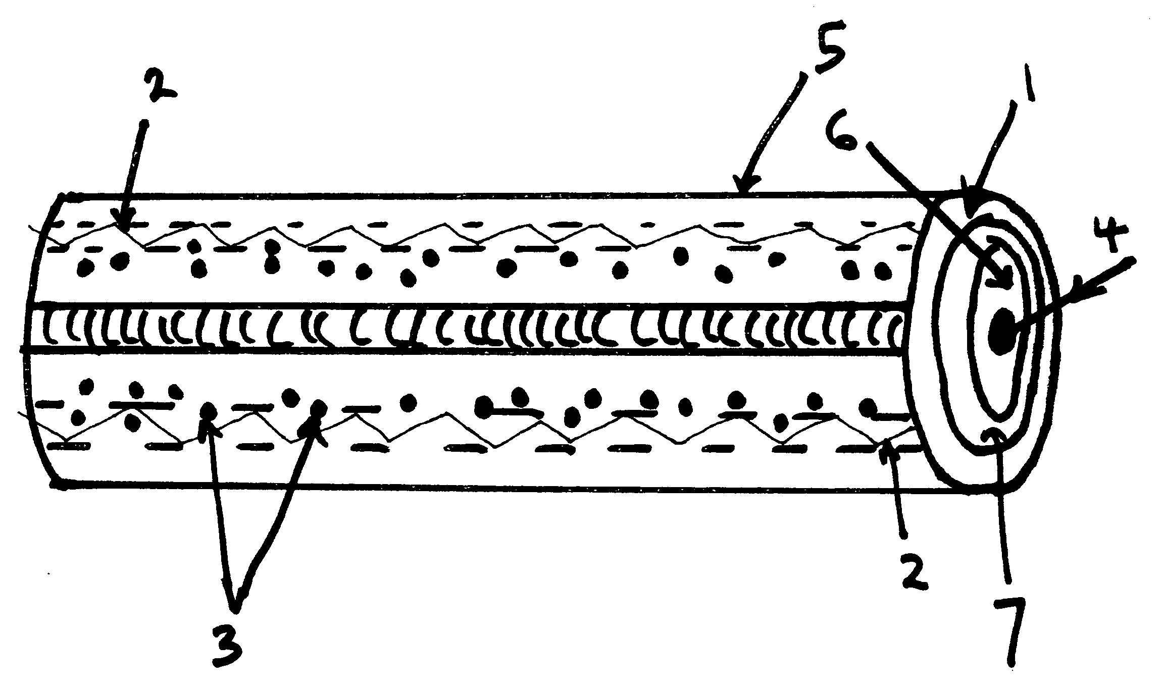
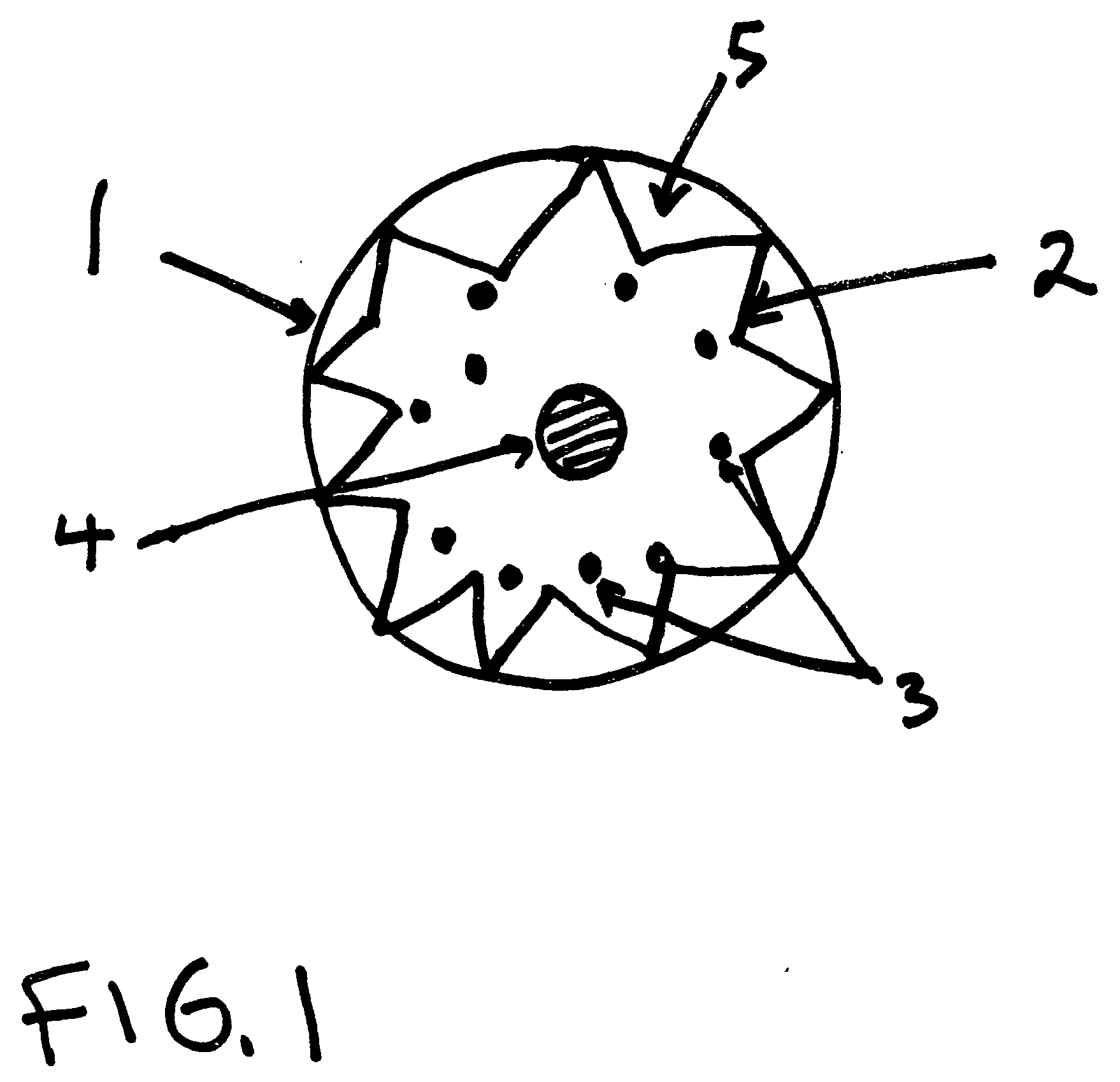
[0018]With reference now to the drawings, and particularly to FIG. 1, there is shown a cross sectional view of a microparticle 1 with electromagnetic radiation or phonon under total internal reflection 2 within microparticle 1. The microparticle 1 is composed of material 5 that allows electromagnetic radiation or phonons to be in total internal reflection 2. The microparticle 1 contains dopants 3 that convert the energy of electromagnetic radiation to vibrational energy or heat. The dopants 3 are immediately at or beneath the lowest point of reflection of the electromagnetic radiation in total internal reflection 2. The heat generated within the microparticle 1 is transferred out of the microparticle 1 by a mechanism 4 that converts heat to electricity or a mechanism that pulls or pushes out the heat.

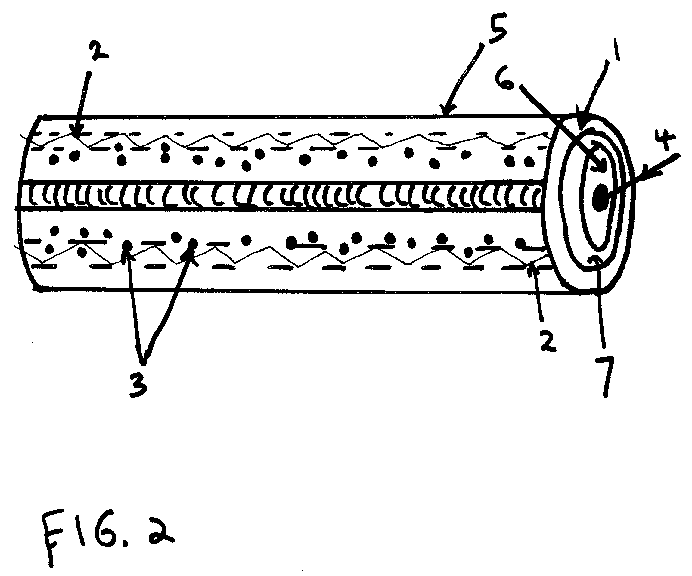
[0019]With reference now to the drawings, and particularly to FIG. 2, there is shown a cross sectional view of an optical fiber 5 with electromagnetic radiation or phonon under total in...


PUM


Abstract

The Total Internal Reflection Energy / Heat Source includes an object that allows electromagnetic radiation or phonons to be in total internal reflection within the object. The object, such as a microparticle or optical fiber, is doped with atoms or molecules that convert the electromagnetic radiation or phonons to heat, where the heat is transferred out of the object or converted to electricity. A second embodiment of the Total Internal Reflection Energy / Heat Source includes an object that allows electromagnetic radiation or phonons to be in total internal reflection within the object. The object, such as a microparticle, contains P-type and N-type materials beneath the surface, where the electromagnetic radiation or phonons in total internal reflection strikes the P-N junction of the P-type and N-type materials creating electricity.

Description

BACKGROUND OF THE INVENTION [0001]1. Field of Invention[0002]The present invention relates generally to the use of total internal reflection in a material to generate heat or electricity.[0003]2. Discussion of Prior Art[0004]Total internal reflection has been used as part of industry and research such as the fiber optic and the microparticle, respectively.[0005]According to Jeff Hecht, City of Light: The Story of Fiber Optics, Oxford University Press 1999, impurities were in the fiber optic were known to reduce the energy transmitting through a fiber optic in Total Internal Reflection. Impurities were reduced to in the fiber optic to reduce the loss of energy.[0006]According to L. M. Folan et al, Enhanced Energy Transfer within a Microparticle, Chemical Physics Letters, Volume 118, Number 3, 26 Jul. 1985 and S. Arnold et al, Energy Transfer and the Photon Lifetime Within an Aerosol Particle, Optics Letters, Vol. 14, No. 8, Apr. 15, 1989, impurities in small water droplets allow for ...

Claims


Application Information

Patent Timeline
Patent Type & Authority Applications(United States)
IPC IPC(8): H01L31/18
CPCG02B6/0229G02B6/4298G02B6/10
Inventor TAMBUNGA, GABRIEL JAMES
Owner TAMBUNGA GABRIEL JAMES
Why Eureka
Try Eureka