Surgical System Including Suture Anchor and Insertion Device and Method for Using

Inactive Publication Date: 2012-03-01
SCHULMAN DANIEL S
View PDF6 Cites 17 Cited by
  • Summary
  • Abstract
  • Description
  • Claims
  • Application Information

AI Technical Summary

Benefits of technology

[0011]The anchor has a retainer formed into the anchor body. The retainer receives a suture and holds the suture in place. In the preferred embodiment, the retainer is a slot formed into the end of the anchor body that goes into the bone, so that the suture is retained behind the anchor when the anchor is installed. One or more channels are formed into the anchor body, running substantially parallel to the axis of the anchor body and connecting to the retainer. The suture may pass th

Problems solved by technology

Additionally, these materials are not bioabsorbable or osteoconductive, so their permanent implantation may prevent the bone from fully healing.
Another drawback with most existing anchors relates to securely fastening the anchor, and thereby the suture, to the bone.
This can traumatize or otherwise damage the living bone when inserted and removed.
If the anchor must be twisted to seat it in the bone, pre-loaded suture will also be twisted, potentially damaging the suture.
While this design may not twist the suture, it may still traumatize or otherwise damage the surrounding bone, and may also damage the anchor due to the force required to fully insert the anchor.
Using an adhesive, however, is potentially messy and expensive, requires an additional step, and may not be an option at all if the anchor is a temporary implant.
While these relatively new implants e

Method used


Image

  • Surgical System Including Suture Anchor and Insertion Device and Method for Using
  • Surgical System Including Suture Anchor and Insertion Device and Method for Using
  • Surgical System Including Suture Anchor and Insertion Device and Method for Using

Examples


Example

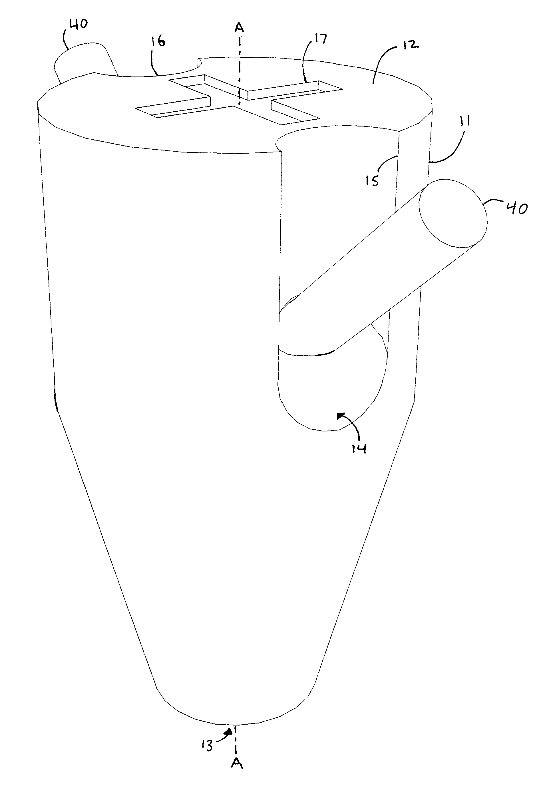
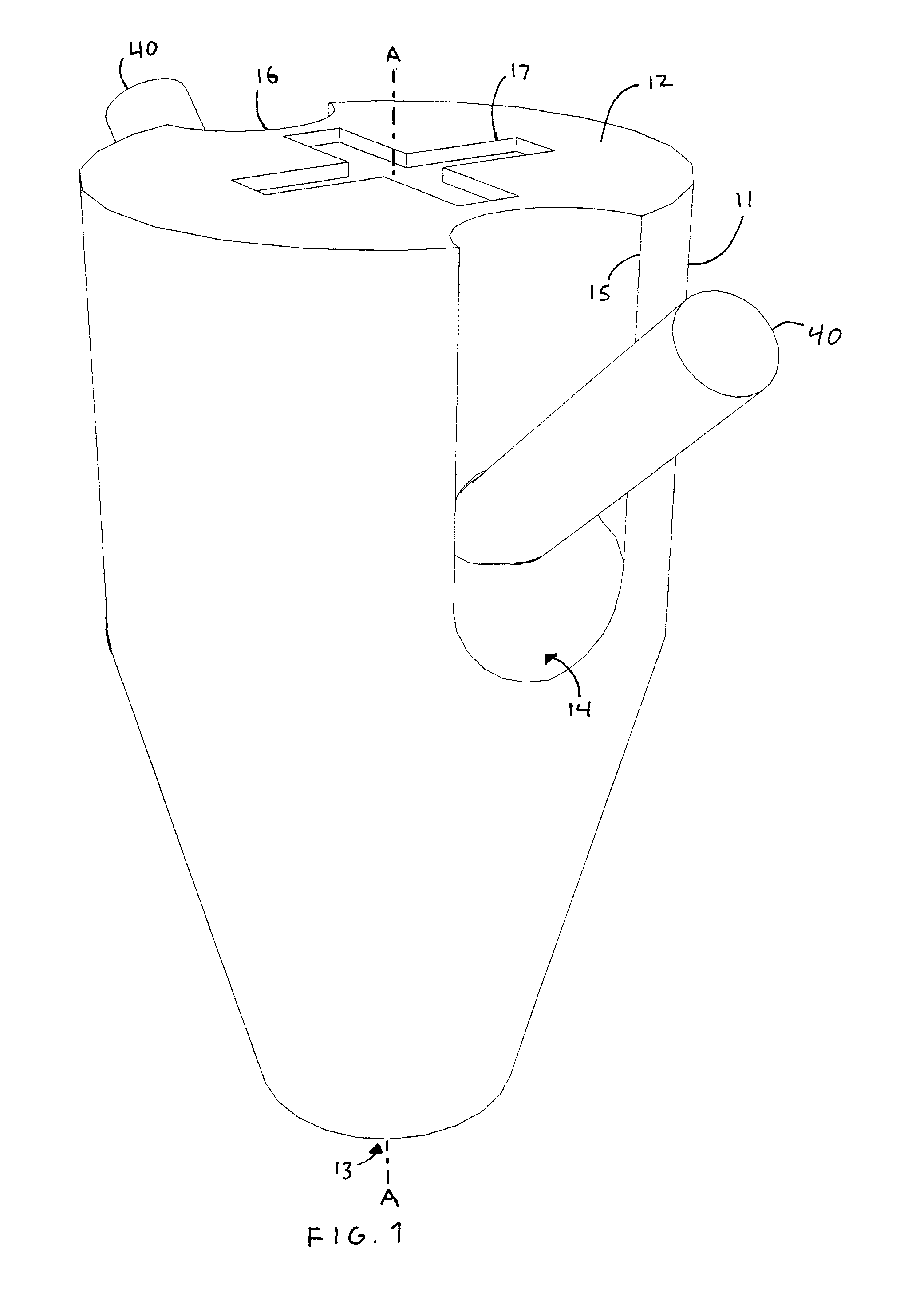
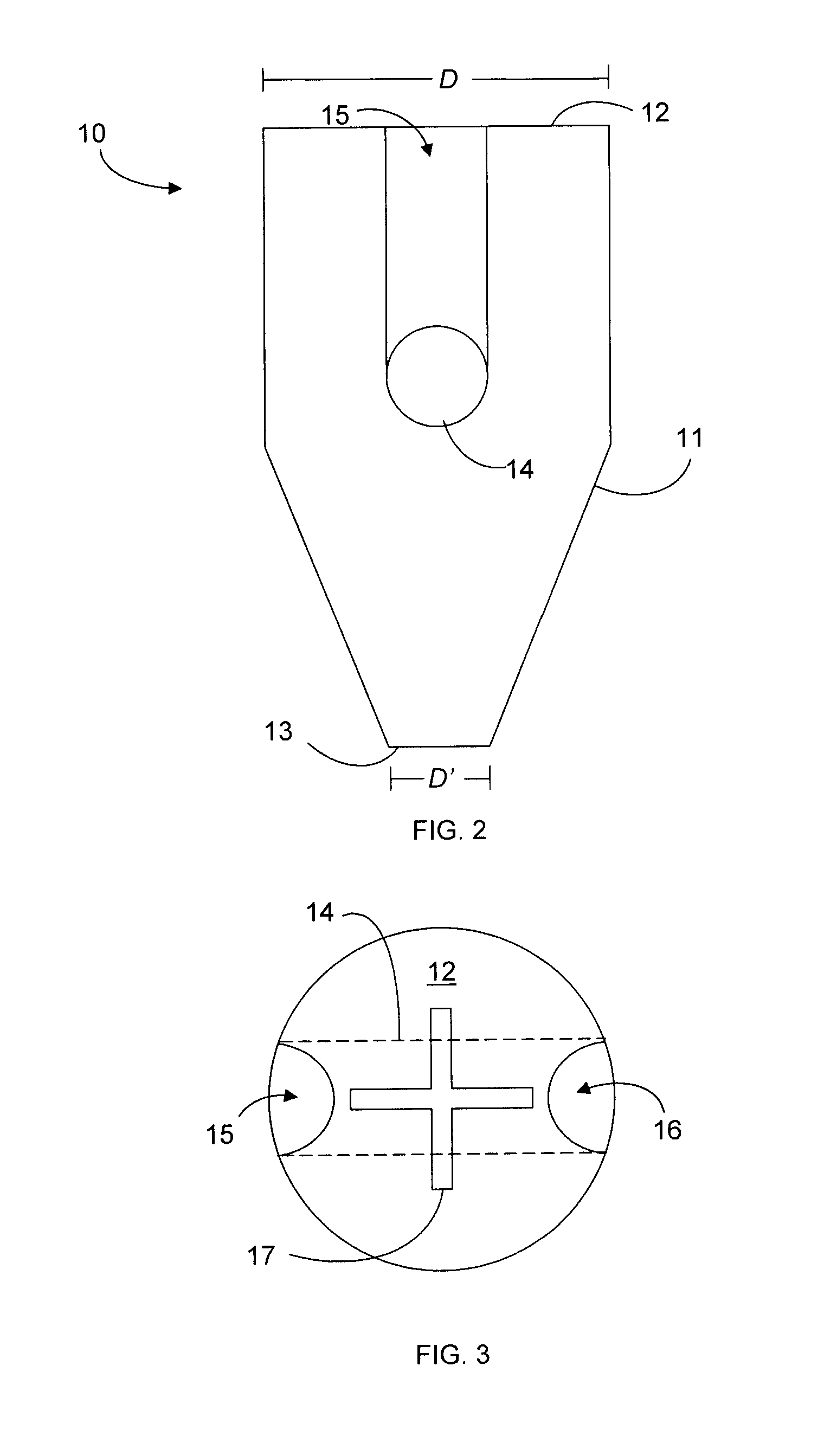
[0024]Referring to FIGS. 1-6, there is illustrated the preferred embodiment of the present invention, designated generally as 10, which is a suture anchor that is implanted in a living bone so that one or more retained sutures 40 may be used to attach tissue to the bone. The anchor 10 comprises an anchor body 11 having a proximal end 12 and a distal end 13. The anchor 10 is inserted into the bone distal end 13 first. The anchor 10 may be any size and shape that is capable of anchoring the target tissue to the target bone, including cylindrical, prism-shaped with any two-dimensional shaped base, pyramidal, conal, or a combination of such shapes. For example, in a first embodiment illustrated in FIGS. 1-3, the anchor body 11 is substantially bullet-shaped, having a cylindrical portion starting at the proximal end 12 and tapering from a first diameter D to a second diameter D′ at the distal end 13. Preferably, the anchor body is cylindrical with planar ends 12, 13 that are orthogonal t...


PUM


Abstract

An improved suture anchor has one or more channels formed into the exterior surface of the anchor body. The channels may be used to inject a compound, such as filler material or an adhesive, into the implant site. Preferably, the channels connect to a retainer in the anchor body for a suture to pass through, preventing the suture from being compressed and allowing removal and adjustment of a suture retained by the anchor after the anchor is installed in a bone. The retainer is preferably a slot formed into the distal end of the anchor body. In a method of securing tissue to bone, an insertion tool is used to insert the suture into the anchor and install the anchor into an implant site in the bone. If the suture later fails, the channels may be used to fill the implant site with bone cement for redrilling. Preferably, the suture anchor is made of human cortical bone or a similarly bioabsorbable and osteoconductive material.

Description

FIELD OF INVENTION[0001]This invention relates to methods and devices for attaching tissue to bone. This invention relates particularly to a suture anchor that is installed in bone.BACKGROUND[0002]The field of orthopedic surgery addresses the need to reattach tissue, particularly connective tissue such as tendons and ligaments, to bone following detachment due to injury or surgery. One approach that is commonly used is to install an implant in the bone at the reattachment site. The tissue is then tied to the implant with one or more lengths of suture. Eventually, the tissue heals by reconnecting to the bone. The implant, known as an anchor, and the sutures may be left in the body or removed.[0003]There are several drawbacks to this procedure. Commonly-used materials for an anchor include metals, plastics, and other nonorganics that may cause adverse biochemical reactions in the body, such as bone and tissue necrosis and other damage, rejection of the implant by the body, and release...

Claims


Application Information

Patent Timeline
IPC IPC(8): A61B17/04
CPCA61B17/0401A61B17/0483A61B17/8805A61B2017/0496A61B2017/0409A61B2017/0414A61B2017/0403
Inventor SCHULMAN, DANIEL S.
Owner SCHULMAN DANIEL S
Why Eureka
Try Eureka