
Actuator for correcting scoliosis

Inactive Publication Date: 2012-03-01
WITTENSTEIN GROUP
View PDF3 Cites 56 Cited by
  • Summary
  • Abstract
  • Description
  • Claims
  • Application Information

AI Technical Summary

Benefits of technology

[0010]Advantages of the invention include, for example, fine adjustability in small steps. This leads to lower distraction and compression forces and to a greater scope of correction by possible tracking or compensation of scoliosis in the growth phase.
[0029]The device preferably comprises a sensor, which is arranged in order to detect a relative movement or a force between the shaft elements. The control means is preferably suitable for processing or transmitting information from the sensor, preferably to a controller arranged outside the body. Moreover, the control means preferably comprises a regulating unit which, on the basis of the sensor signal, controls the electric motor in order to reach a predefined force value or movement value. It is likewise possible to establish the control loop via an external controller. This affords the advantage of an exact adjustment.

Problems solved by technology

The treatment in each case is complex and lengthy, since the geometry of the spinal column can be changed only over a long period of time.
A problem, however, is that the vertebral bodies stiffen as a result of ossification or similar processes, and in some circumstances this can lead to a complete loss of mobility or to further growth being prevented.
A disadvantage of this approach is that readjustment of the implant is regularly required.
This necessitates surgical interventions under general anesthesia, and, in particular because of the short times between interventions, this can place a significant psychological strain on the patient.
All of the correcting methods known to date have the disadvantage that each correction has to be performed in one session, and the scope of correction is greatly limited by this.
The reason for this limitation is the slow biological adaption process.
However, for various reasons, all of the drives that have hitherto been proposed and are implantable have been used only to a limited extent in practice.
In particular, it has hitherto been difficult to achieve a sufficient force with a sufficient stroke of the implant.

Method used


Image

  • Actuator for correcting scoliosis
  • Actuator for correcting scoliosis
  • Actuator for correcting scoliosis

Examples


Embodiment Construction

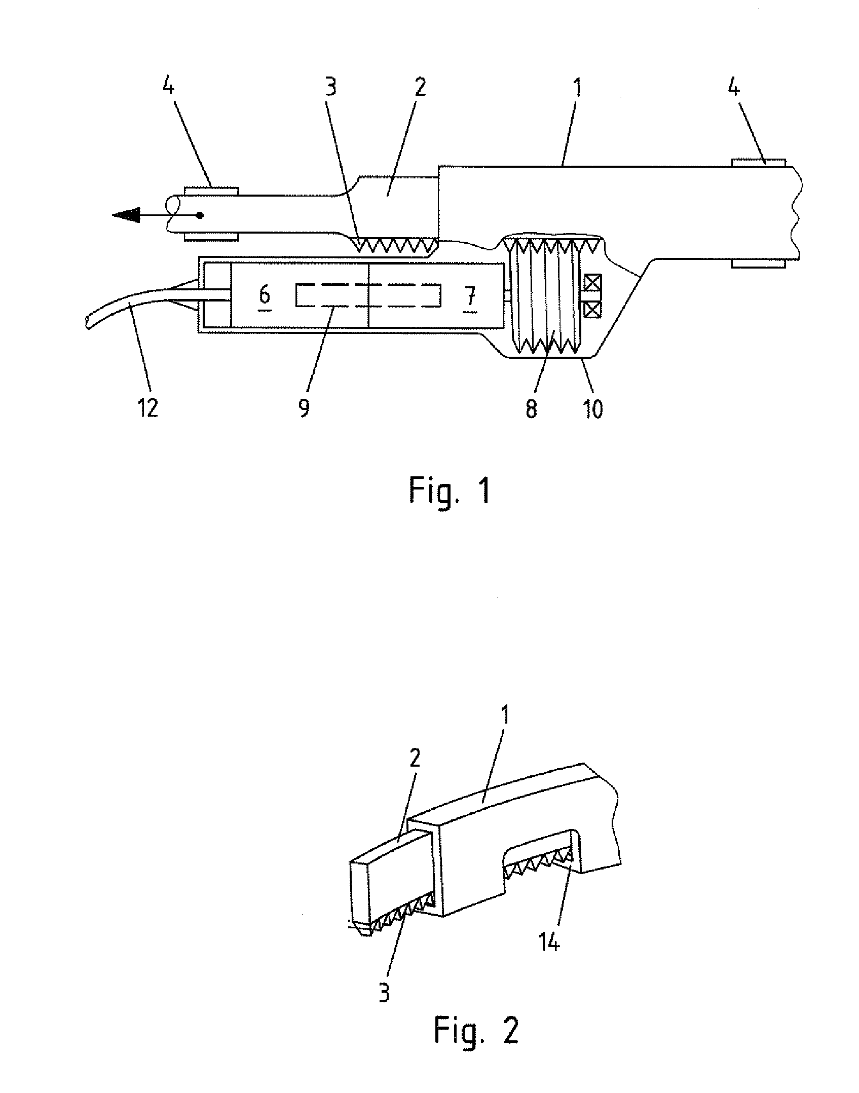
[0036]FIG. 1 shows a preferred embodiment of a device according to the invention in a schematic and partially sectioned view.

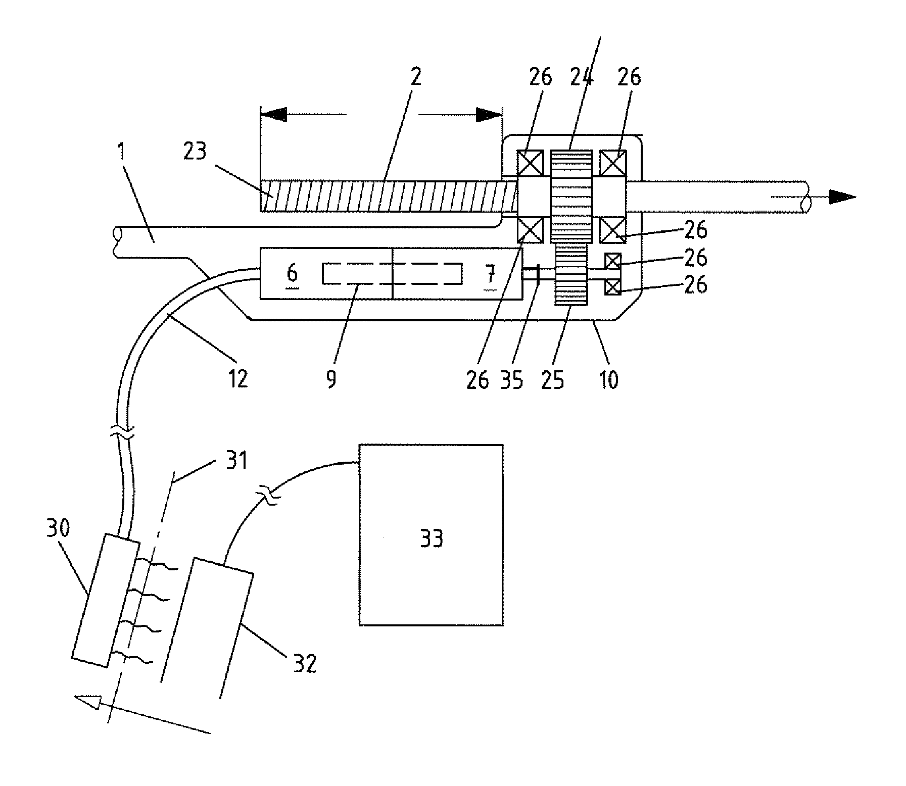
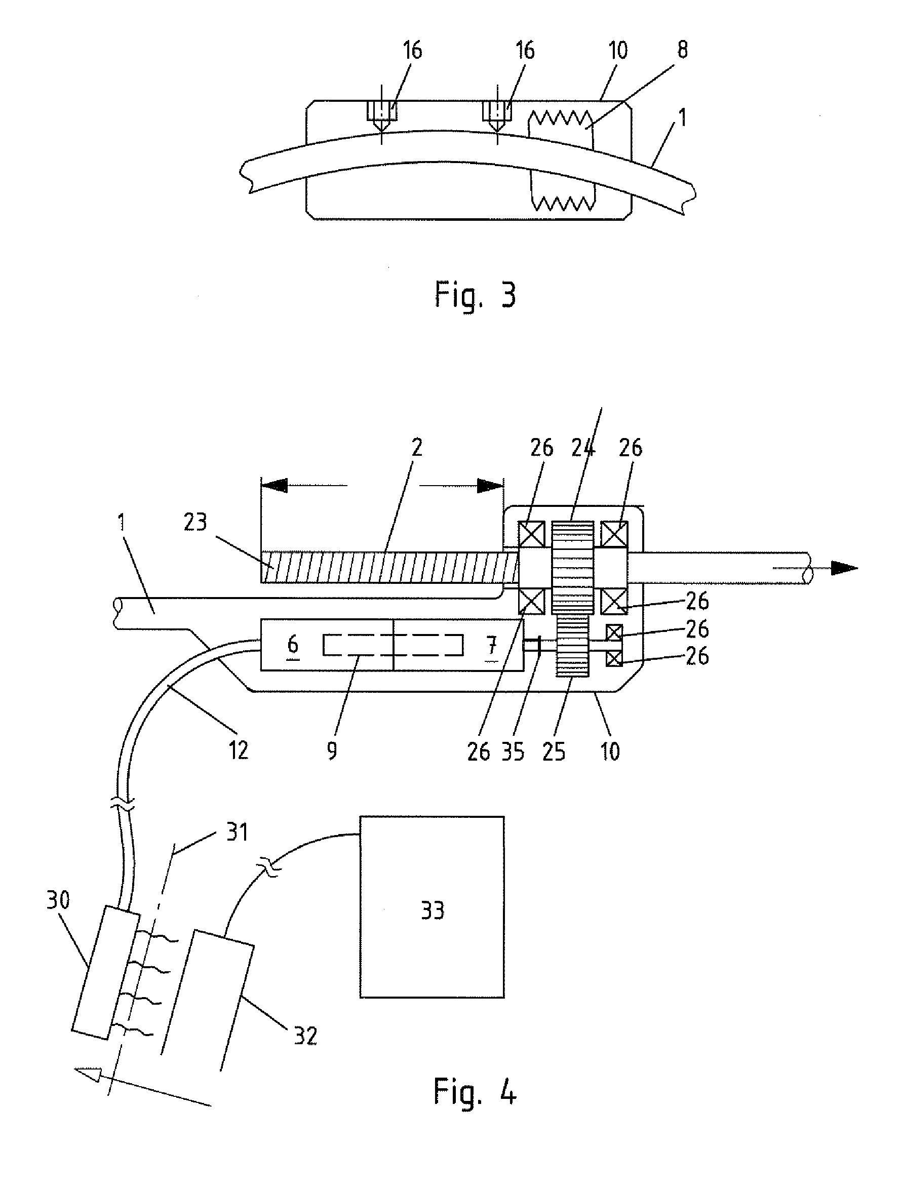
[0037]The device according to the invention in FIG. 1 comprises a first shaft element 1 and a second shaft element 2. The second shaft element 2 integrally comprises a toothed rack 3. The toothed rack 3 forms the second shaft element 2. The respective ends of the shaft elements 1 and 2 are provided with bone fasteners 4, which are designed to engage in costal arches. In the direction of an arrow shown in FIG. 1, the second shaft element 2 is movable relative to the first shaft element 1 in both senses, i.e. bidirectionally. To obtain such a movement, an electric motor 6 is used, which drives a worm wheel 8 via a planetary gear 7 with a transmission ratio. The worm wheel 8 is driven via an output shaft 9 (shown by broken lines) of the electric motor 6 and via the planetary gear 7. The electric motor 6, the planetary gear 7 and the worm wheel 8 are arranged in a...


PUM


Abstract

Device for the relative movement of bones, in particular for the treatment of scoliosis in humans, with a first shaft element (1), a second shaft element (2), which is connected movably to the first shaft element (1), and an electric motor, which is connected to the first shaft element (1), wherein an output shaft of the electric motor is operatively connected to the second shaft element (2) in order to permit a movement of the shaft elements (1, 2) relative to each other, wherein the electric motor (6) is arranged lengthways adjacent to at least one of the shaft elements (1, 2).

Description

BACKGROUND OF THE INVENTION[0001]The invention relates to a device for the relative movement of bones, in particular to an implant for the treatment of scoliosis in humans.[0002]Implants for treating scoliosis are known from the prior art. Scoliosis is a disease of the spinal column in which severe deformations of the spinal column occur. These deformations are generally treated mechanically, in which respect a distinction is made in principle between external treatment methods using a corset and treatment methods using implants. The treatment in each case is complex and lengthy, since the geometry of the spinal column can be changed only over a long period of time. For example, when treatment is provided with a corset, it is assumed that, if the corset is worn for up to 23 hours a day, it will take two to five years before scoliosis treatment with the corset is completed.[0003]Treatments with implants have the advantage that the corset does not need to be worn, and therefore the tr...

Claims


Application Information

Patent Timeline
IPC IPC(8): A61F5/00
CPCA61B17/7016A61B2017/00039A61B2017/0011A61B2019/464A61B2017/00398A61B2017/00867A61B2019/461A61B2017/00221A61B2090/061A61B2090/064
Inventor STAUCH, ROMAN
Owner WITTENSTEIN GROUP
Learn More