
Method for detecting atypical electronic components

a technology of electronic components and detection methods, applied in the field of detecting atypical electronic components, can solve the problems of defective components, components that are rejected and therefore not delivered to customers, and can have latent defects that will be revealed

Inactive Publication Date: 2012-03-01
IPPON INNOVATION
View PDF5 Cites 1 Cited by
  • Summary
  • Abstract
  • Description
  • Claims
  • Application Information

AI Technical Summary

Benefits of technology

[0018]The objective of this invention is therefore to propose a method making it possible to refine the detection of atypical (and therefore potentially defective) electronic components in a set of electronic components subjected to a large number of tests so as to get close to zero defect, in accordance with the requirements of, for example, the automotive industry.
[0021]According to a fourth purpose of the invention, in some cases it can allow manufacturers of electronic components to eliminate costly reliability tests, known as “burn-in”, as parts rejected during this burn-in are picked up by our invention.DESCRIPTION OF THE INVENTION
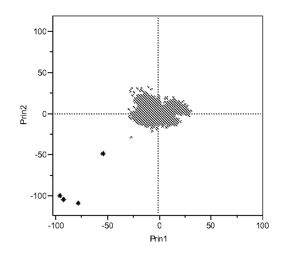
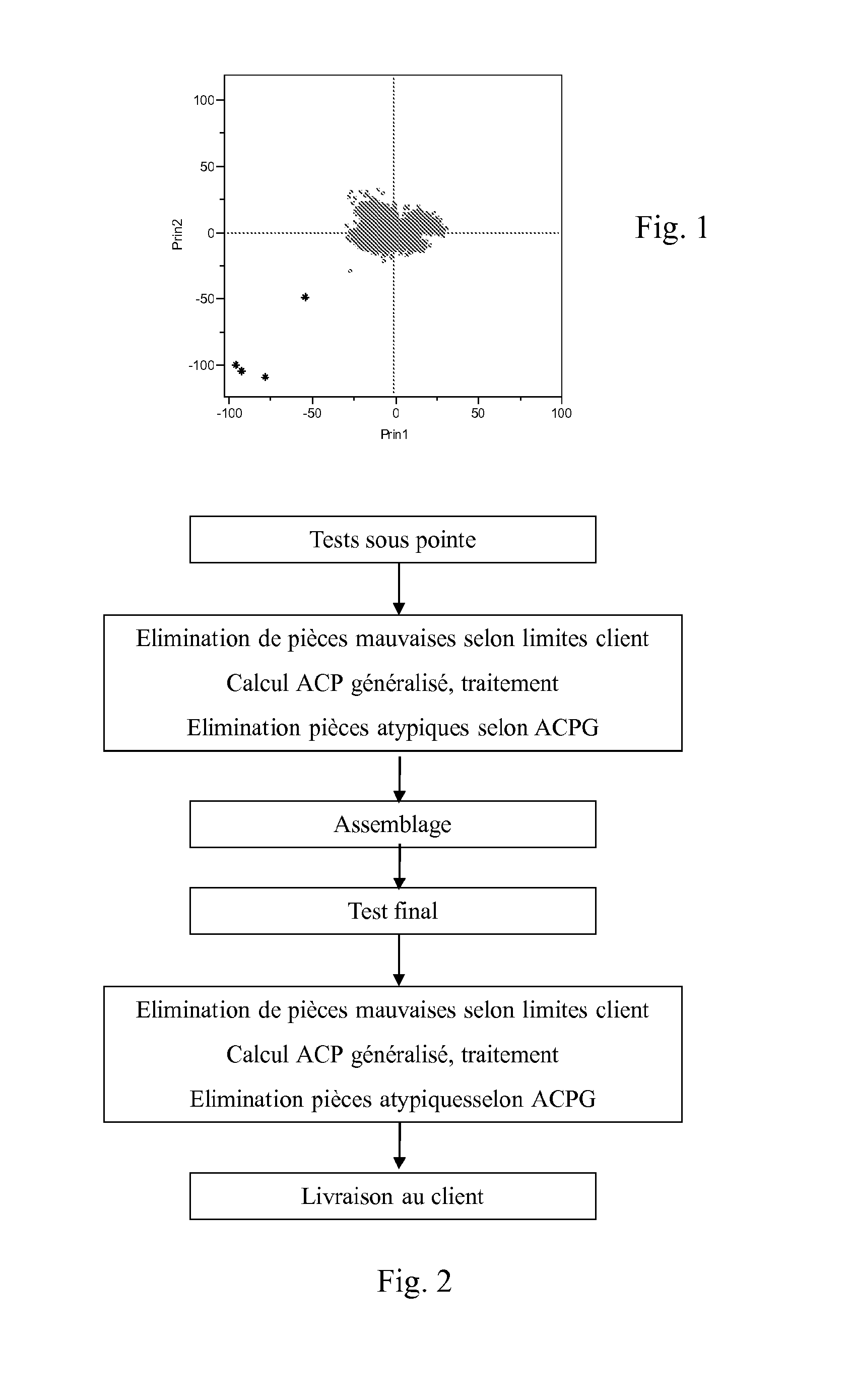
[0026]Using Principal Component Analysis significantly reduces the number of work dimensions, while retaining a very significant portion of the information present in the initial point cluster, each point corresponding to a result of a test for an electronic component. The information extracted will be enough to characterize a structure of n electronic components and thus reveal the atypical electronic components.

Problems solved by technology

Electronic components for which the response to at least one test does not comply with the specifications for this test of this first test series (probe), are therefore considered defective and are rejected when they are separated from the wafer.
Thus, with this commonly used method, a component is rejected and therefore not delivered to the customer if at least one response to a test (in the first or second series of tests) is outside the specification limits associated with this test.
However, parts that have been delivered, and therefore have passed all the tests successfully, can have a latent defect that will be revealed when the part is utilized as part of the client's application, on delivery or later in the final application (an ABS brake for example).
This quality control, as currently usually practiced, thus appears insufficient and some supplemental methods have already been implemented, for instance in components designed for the automotive industry, to minimize these quality problems experienced by the client.
There is therefore a tendency to consider that the component surrounded by defective components is probably defective through “geographical” proximity.
However, these supplemental methods, while constituting improvements relative to previous test methods, still have drawbacks.
This disadvantage is a problem, firstly because it forces the manufacturer to send the customer a new batch of replacement parts and reduces the client's perception of its quality level, and even more so because some of these components, although with a low unit cost, are critical components in the working of a more complex system, such as a motor controller or an ABS braking system.
In this case, a component failure can lead to a serious accident whose consequences go far beyond the mere financial value of the component.
This risk leads manufacturers to choose to reject too many components, including many good components, because they use the univariate (PAT, etc.) or bivariate (regression, etc.) methods over a very large number of tests, which deprives them of a few percent of their production, while still not guaranteeing to eliminate all the potentially defective components.
Although these methods already have a certain level of performance, they are therefore insufficient to achieve zero defects.

Method used


Image

  • Method for detecting atypical electronic components
  • Method for detecting atypical electronic components
  • Method for detecting atypical electronic components

Examples


Embodiment Construction

[0022]To this end, the invention envisages a method for detecting atypical electronic components for the quality control of a set of n electronic components at the end of the manufacturing process, said components being subject to a number p of unit tests providing digital data, this set of n components consisting of electronic components whose response to each of the p unit tests is contained within pre-defined limits, called customer specification limits, and specific to each of the p tests, using the multidimensional information of these n electronic components' responses of dimension p.

[0023]It is understood that unlike the state of the art, which works in one or two dimensions, this method will work in p dimensions and thus will be able to use all the information from the p tests, and consequently identify more atypical components or call into question some rejected components.

[0024]Indeed, for the majority of atypical components, their latent defect is detectable in the atypia...


PUM


Abstract

A method for detecting atypical electronic components for the quality control of a set of n electronic components at the end of the manufacturing process, the components being subject to a number p of unit tests providing digital data, this set of n components consisting of electronic components whose response to each of the p unit tests is contained within pre-defined limits specific to each of the p tests, uses the multidimensional information of the p dimension responses of these n electronic components. The method uses a generalized principal component analysis for detecting atypical items in the semiconductor field, or in fields including modules assembled using electronic components (e.g. an ABS module, a smart card, etc.). The aim of the method is to get close to “zero defect”, in which no parts are detected as non-compliant by the client.

Description

[0001]The present invention relates to the field of the quality control of parts and electronic components in particular.BACKGROUND OF THE INVENTION AND PROBLEM STATEMENT[0002]The semiconductor industry produces integrated circuits, called electronic components, which are manufactured on groups of silicon wafers; each wafer comprises several hundred components.[0003]To guarantee the working of these electronic components a first series of tests, called probe tests, is performed on each of the components while they are still part of a wafer.[0004]Each of these tests, which respectively consist of an electronic measurement, is associated with a specification limit determined, amongst others, with the client for whom the electronic components are destined.[0005]Electronic components for which the response to at least one test does not comply with the specifications for this test of this first test series (probe), are therefore considered defective and are rejected when they are separat...

Claims


Application Information

Patent Timeline
IPC IPC(8): G06F19/00
CPCG01R31/2894
Inventor BERGERET, FRANCOISRUIZ, ANNESOUAL, CAROLECAUSSINUS, HENRI
Owner IPPON INNOVATION
Learn More