Angular velocity detection apparatus and electronic instrument

a technology of angular velocity and detection apparatus, applied in the direction of speed/acceleration/shock measurement device, speed/calibration testing/calibration, instruments, etc., can solve problems such as wrong control of electronic instruments or systems

Active Publication Date: 2012-03-08
SEIKO EPSON CORP
View PDF11 Cites 28 Cited by
  • Summary
  • Abstract
  • Description
  • Claims
  • Application Information

AI Technical Summary

Problems solved by technology

Such an electronic instrument or system performs wrong control if the angular velocity detection apparatus breaks down.

Method used


Image

  • Angular velocity detection apparatus and electronic instrument
  • Angular velocity detection apparatus and electronic instrument
  • Angular velocity detection apparatus and electronic instrument

Examples


second embodiment

1-2. Second Embodiment

[0128]In the examples illustrated in FIGS. 7A to 7C and FIGS. 8A to 8C, the temperature characteristics of the angular velocity signal 36a is similar to the temperature characteristics of the vibration leakage signal 36b. FIG. 12 illustrates an example of temperature characteristics that differ in tendency from those illustrated in FIGS. 7A to 7C and FIGS. 8A to 8C. In FIG. 12, the horizontal axis indicates time, and the vertical axis indicates voltage. In FIG. 12, the solid line indicates the temperature characteristics of the angular velocity signal 36a, and the broken line indicates the temperature characteristics of the vibration leakage signal 36b.

[0129]In FIG. 12, the temperature characteristics of the angular velocity signal 36a and the temperature characteristics of the vibration leakage signal 36b differ in second-order component and third-order component to only a small extent, but differ in first-order component to a large extent. Therefore, the tem...

third embodiment

1-3. Third Embodiment

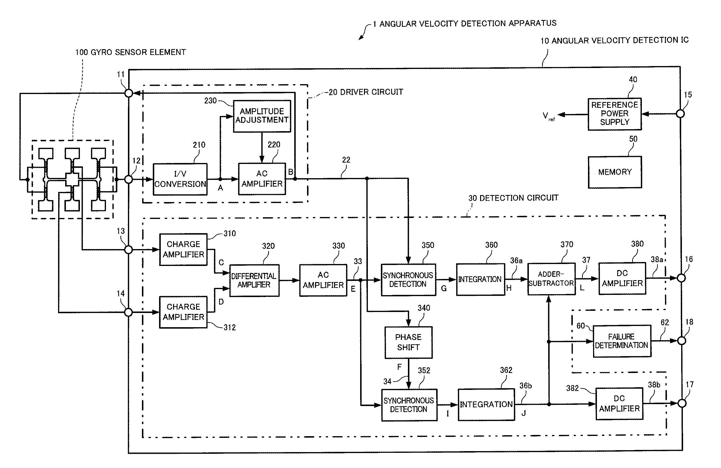
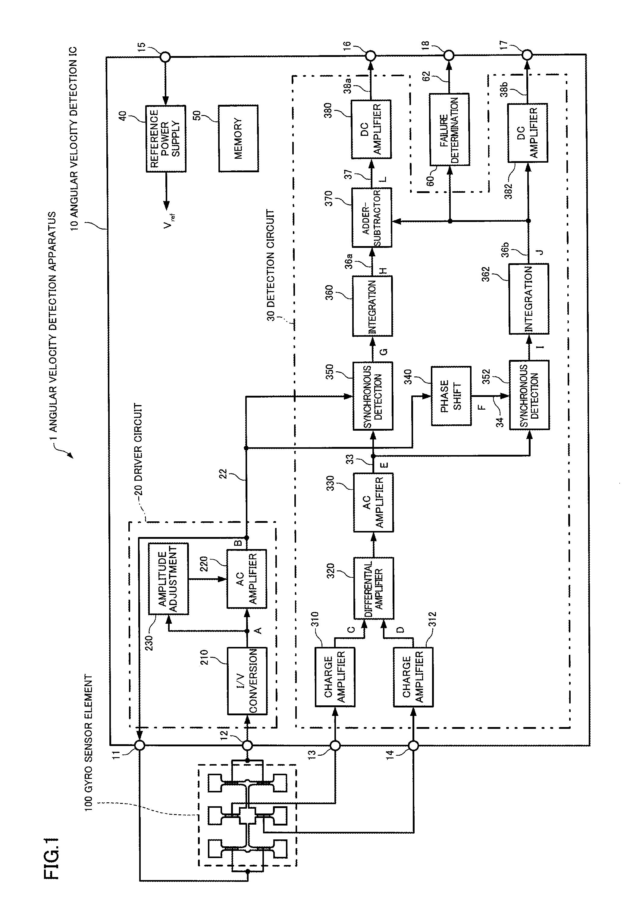
[0144]FIG. 16 is a diagram illustrating a configuration example of an angular velocity detection apparatus according to a third embodiment of the invention. In FIG. 16, the same sections as those illustrated in FIG. 13 are indicated by the same symbols. Description of these sections is omitted.

[0145]An angular velocity detection apparatus 1 according to the third embodiment has a configuration in which the first-order temperature adjustment circuit 390 is omitted from the configuration illustrated in FIG. 13. The first-order temperature adjustment circuit 392 adjusts the first-order component of the temperature characteristics of the vibration leakage signal 36b to approach the first-order component of the temperature characteristics of the angular velocity signal 36a based on the temperature detection signal 72. The first-order temperature adjustment circuit 392 may be configured in the same manner as in FIG. 14. The first-order temperature adjustment circuit 3...

fourth embodiment

1-4. Fourth Embodiment

[0149]FIG. 18 is a diagram illustrating a configuration example of an angular velocity detection apparatus according to a fourth embodiment of the invention. In FIG. 18, the same sections as those illustrated in FIG. 13 are indicated by the same symbols. Description of these sections is omitted.

[0150]An angular velocity detection apparatus 1 according to the fourth embodiment differs from the configuration illustrated in FIG. 13 in that the first-order temperature adjustment circuits 390 and 392 are omitted, and a first-order temperature correction circuit 398 is added in the subsequent stage of the adder-subtractor circuit 370. The first-order temperature correction circuit 398 corrects the first-order component of the temperature characteristics of the angular velocity signal 37 based on the temperature detection signal 72. The first-order temperature correction circuit 398 may be configured in the same manner as in FIG. 14. The first-order temperature correc...


PUM


Abstract

An angular velocity detection apparatus includes a vibrator that generates a signal that includes an angular velocity component and a vibration leakage component, a driver section that generates the drive signal, and supplies the drive signal to the vibrator, an angular velocity signal generation section that extracts the angular velocity component from the signal generated by the vibrator, and generates an angular velocity signal corresponding to the magnitude of the angular velocity component, a vibration leakage signal generation section that extracts the vibration leakage component from the signal generated by the vibrator, and generates a vibration leakage signal corresponding to the magnitude of the vibration leakage component, and an adder-subtractor section that adds the vibration leakage signal to the angular velocity signal, or subtracts the vibration leakage signal from the angular velocity signal, in a given ratio to correct temperature characteristics of the angular velocity signal.

Description

[0001]Japanese Patent Application No. 2010-199791, filed on Sep. 7, 2010, is hereby incorporated by reference in its entirety.BACKGROUND OF THE INVENTION[0002]The present invention relates to an angular velocity detection apparatus and an electronic instrument.[0003]An electronic instrument or a system that includes an angular velocity detection apparatus, and performs a predetermined control process based on the angular velocity detected by the angular velocity detection apparatus has been widely used. For example, a vehicle travel control system prevents a side skid, or detects an overturn, based on the angular velocity detected by the angular velocity detection apparatus.[0004]Such an electronic instrument or system performs wrong control if the angular velocity detection apparatus breaks down. Therefore, measures such as lighting an alarm lamp when the angular velocity detection apparatus has broken down have been employed. Various technologies that diagnose failure of the angul...

Claims


Application Information

Patent Timeline
Patent Type & Authority Applications(United States)
IPC IPC(8): G01P21/00G01P3/00
CPCG01C19/5726G01P21/00G01C19/5776
Inventor NARUSE, HIDETOSATO, KENJITAKADA, YUTAKA
Owner SEIKO EPSON CORP
Why Eureka
Try Eureka