Optical allocation for dynamic gain balancer and adder-subtractor

A technology of optical equipment, light beams, applied in the field of optical configurations including diffraction gratings, capable of solving problems such as inability to realize advantages

Inactive Publication Date: 2004-07-07
LUMENTUM OPERATIONS LLC
View PDF3 Cites 1 Cited by
  • Summary
  • Abstract
  • Description
  • Claims
  • Application Information

AI Technical Summary

Problems solved by technology

However, the device disclosed here is only suitable for a single pass through a diffraction grating and cannot achieve the advantages of the invention

Method used


Image

  • Optical allocation for dynamic gain balancer and adder-subtractor
  • Optical allocation for dynamic gain balancer and adder-subtractor
  • Optical allocation for dynamic gain balancer and adder-subtractor

Examples


Embodiment Construction

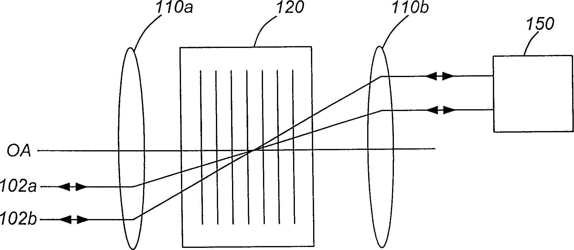
[0051] now refer to figure 1 , shows an optical device for rerouting and correcting optical signals according to the present invention, which can be used as a dynamic gain / channel equalizer (DGE) and / or a configurable optical add / drop multiplexer (COADM ).

[0052] The optical design includes a diffractive element 120 positioned at the focal plane between identical elements 110a and 110b each having an optical power. Two ports 102a and 102b are shown at the input / output ends, and the double-headed arrow indicates that light emitted to port 102a can be transmitted through the optical device and reflected back to input port 102a from which the light was emitted, or switched in a controllable manner to port 102b and vice versa. The input / output ports 102a and 102b are also disposed in the focal plane of the power device 110a coupled thereto. Although only two input / output ports are shown to facilitate understanding of the device, multiple such port pairs may alternatively be p...


PUM


Abstract

An optical device for rerouting and modifying an optical signal is disclosed. The optical design includes a front-end unit for providing a collimated beam of light, an element having optical power for providing collimating / focusing effects, a diffraction element for providing spatial dispersion, and modifying means which in a preferred embodiment includes one of a MEMS array and a liquid crystal array for reflecting and modifying at least a portion of a beam of light. The modifying means functions as an attenuator when the optical device operates as a DGE and as a switching array when the optical device operates as a COADM.

Description

technical field [0001] The present invention relates to an optical device for rerouting and correcting an optical signal, or more particularly to an optical arrangement comprising a diffraction grating that can be used as a dynamic gain equalizer and / or a configurable add / subtract multiplexer. Background technique [0002] In an optical wavelength division multiplexing (WDM) communication system, an optical waveguide simultaneously transmits a plurality of different communication channels according to different wavelengths. In a WDM system, it is desirable to verify that all channels have approximately the same power. To achieve this, gain equalizers are placed at various points throughout the system to control the corresponding power levels of the corresponding channels. [0003] Dense WDM systems require special add / drop multiplexers (ADMs) to add and remove specific channels (ie, wavelengths). For example, at predetermined nodes in the system, optical signals of predet...

Claims


Application Information

Patent Timeline
Patent Type & Authority Patents(China)
IPC IPC(8): G02B6/34
CPCG02B6/29313G02B6/2931G02B6/2773G02B6/29397G02B6/2793G02B6/2766G02B6/29383G02B6/29395
Inventor 奥列格·布耶维奇托马斯·杜斯利尔W·约翰·汤姆林森保罗·科尔波尼
Owner LUMENTUM OPERATIONS LLC
Why Eureka
Try Eureka