
Mapping module-based 16-bit adder-subtractor design method

A technology of mapping modules and adders and subtracters, which is applied in calculations using number system representations, calculations using non-contact manufacturing equipment, etc., can solve problems such as the instability of NOT gates, the increase in the scale and design complexity of DNA computers, etc. , to achieve the effect of avoiding instability, fewer layers, and a single structure

Active Publication Date: 2016-11-16
DALIAN UNIVERSITY
View PDF6 Cites 1 Cited by
  • Summary
  • Abstract
  • Description
  • Claims
  • Application Information

AI Technical Summary

Problems solved by technology

[0003] Winfree solves the problem of NOT gate instability through dual-rail logic. The AND gate module, OR gate module and fan-out gate module he designed can be combined with dual-rail logic to design many stable DNA logic circuits, but the scale of dual-rail logic circuits is single-rail 2 times that of logic circuits, which increases the size and design complexity of DNA computers

Method used


Image

  • Mapping module-based 16-bit adder-subtractor design method
  • Mapping module-based 16-bit adder-subtractor design method
  • Mapping module-based 16-bit adder-subtractor design method

Examples


Embodiment 1

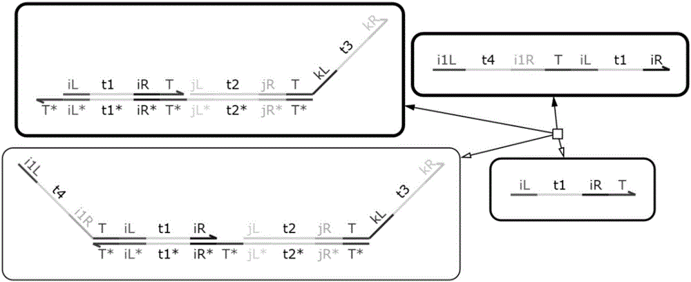
[0046] The embodiments of the present invention are implemented on the premise of the technical solutions of the present invention, and detailed implementation methods and specific operation processes are given, but the protection scope of the present invention is not limited to the following embodiments. Because the domain label 1 input mapping module, domain label 2 input mapping module, and domain label 3 input mapping module in the present invention are used as the basic logic operation modules of DNA logic circuits, they can be combined and designed into other DNA logic circuits. The present invention takes a 16-bit adder-subtractor as an example.

[0047] Step 1: Use domain t and domain f to mark the DNA strand, domain t and domain f represent logic 1 and logic 0, respectively, and construct a domain-labeled DNA signal chain (input-output chain). The DNA signal chain is structurally symmetrical, and its left half can perform DNA strand displacement reactions with the cor...


PUM


Abstract

The invention relates to a method for designing a 16-bit adder-subtractor by utilizing mapping modules, and belongs to the technical field of computer application. The method comprises the following steps of 1: marking a DNA strand by utilizing a domain t and a domain f that represent logic 1 and logic 0 respectively, and establishing a domain-marked DNA signal strand that achieves a medium effect of transferring a signal in a DNA strand displacement reaction, wherein an input / output strand is the DNA signal strand, the DNA signal strand is symmetric in structure, the left half side of the DNA signal strand and a corresponding module of an upstream part can be subjected to the DNA strand displacement reaction, and the right half side of the DNA signal chain and a corresponding module of a downstream part can be subjected to the DNA strand displacement reaction; 2: establishing domain-marked 1 input-mapping modules; and 3: establishing domain-marked 2 input-mapping modules. The logic 1 and the logic 0 are represented through the domain t and the domain f respectively, so that the certainty of the reaction is enhanced and the instability caused by the fact that logic values are represented by concentration is avoided.

Description

technical field [0001] The invention relates to a method for designing a 16-bit adder and subtractor by using a mapping module, and belongs to the technical field of computer applications. Background technique [0002] Seelig used DNA chains to design AND gates, OR gates, and NOT gates. These three modules can be used to combine the DNA logic circuits of DNA computers. The Boolean value in the circuit is represented by the presence or absence of DNA chains. However, the NOT gate designed by Seelig is not stable, and the logic circuit designed by the NOT gate is prone to error signals, which cannot make a stable DNA computer. Winfree constructed the AND gate module, the OR gate module and the fan-out gate module, and combined them with dual-rail logic to design a 4-bit square root DNA logic circuit. The Boolean value of the circuit is represented by the concentration of the DNA chain. [0003] Winfree solves the problem of NOT gate instability through dual-rail logic. The AN...

Claims


Application Information

Patent Timeline
IPC IPC(8): G06F7/50
CPCG06F7/50
Inventor 张强杨乾浩周昌军魏小鹏
Owner DALIAN UNIVERSITY
Learn More