Phased array ultrasonic inspection system for turbine and generator rotor bore

a phased array and ultrasonic inspection technology, applied in the direction of vibration measurement in solids, instruments, specific gravity measurement, etc., can solve the problems of large safety margin, two-dimensional view of material, and the consequences of sudden catastrophic failure of such a componen

Active Publication Date: 2012-03-08
SIEMENS ENERGY INC
View PDF11 Cites 14 Cited by
  • Summary
  • Abstract
  • Description
  • Claims
  • Application Information

AI Technical Summary

Problems solved by technology

Other methods, such as visual and magnetic particle examination, have been used successfully to inspect the bore, but some of these methods are only sensitive to discontinuities which intersect or are very near to the bore and then only yield a two-dimensional view of the material and any detected discontinuities.
The consequences of a sudden, catastrophic failure of such a component could be severe.
However, there are instances where a large margin of safety is built into the analysis to compensate for the lack of accuracy and resolution of the inspection data.
While this approach is safe, it can be inefficient in that the component actually may be able to operate safely for a period of time that extends beyond that identified by a conservative assessment.
Although drilling the bore hole is a mechanism for removing most of the impurities, the bore hole can be stressed during operation of the rotor, which can lead to discontinuities in the rotor material.
Additionally, other impurities or inclusions that remained outside of the bored area (volume) could grow under service-related stress and could potentially result in a failure.
Transducer and wedge change out is time consuming and requires numerous wedges and transducers to sweep through several different angles of attack.
The capabilities of known systems have limitations.

Method used


Image

  • Phased array ultrasonic inspection system for turbine and generator rotor bore
  • Phased array ultrasonic inspection system for turbine and generator rotor bore
  • Phased array ultrasonic inspection system for turbine and generator rotor bore

Examples


example

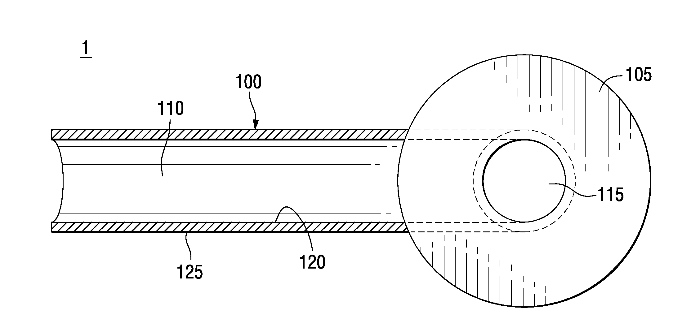
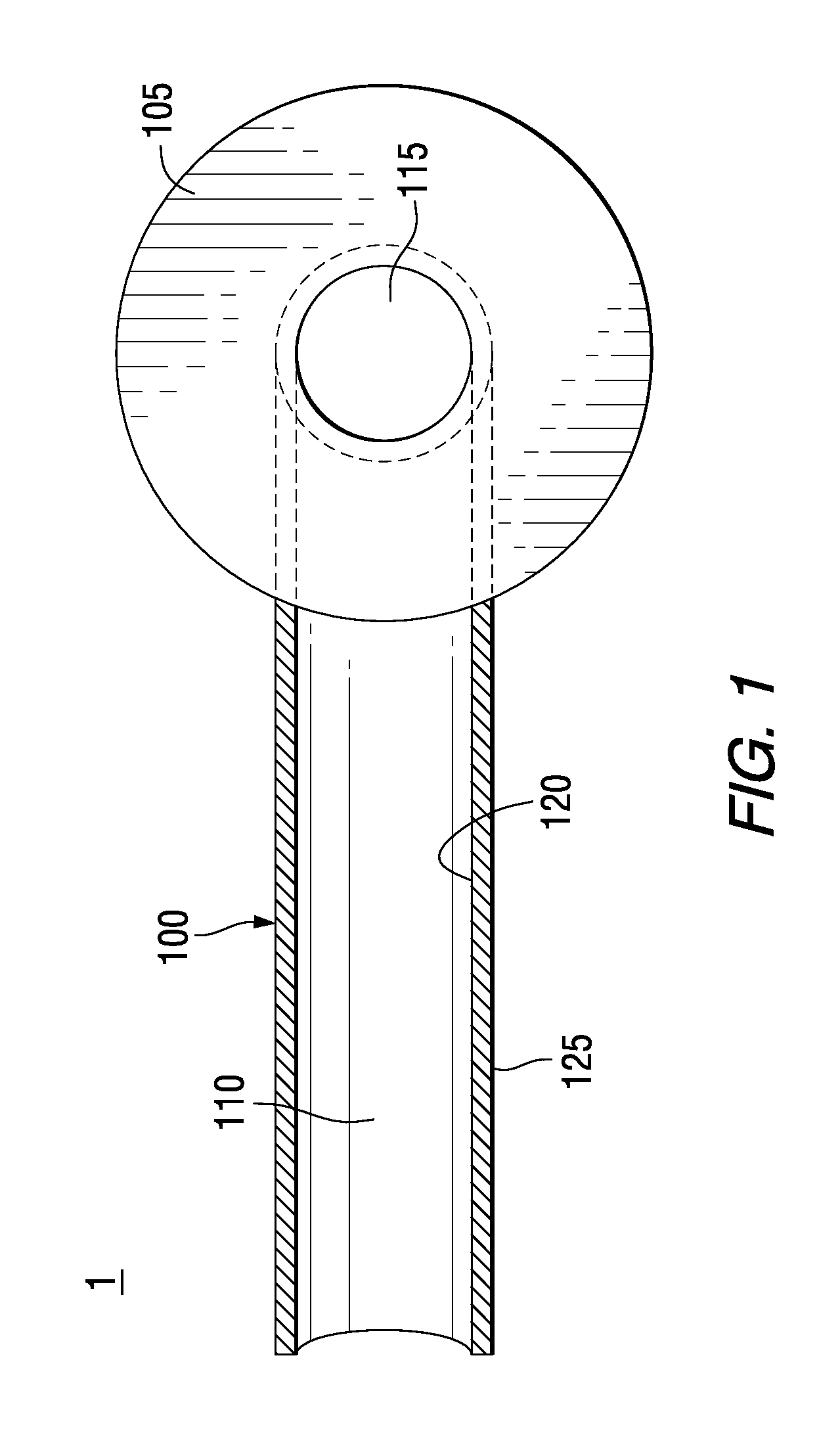
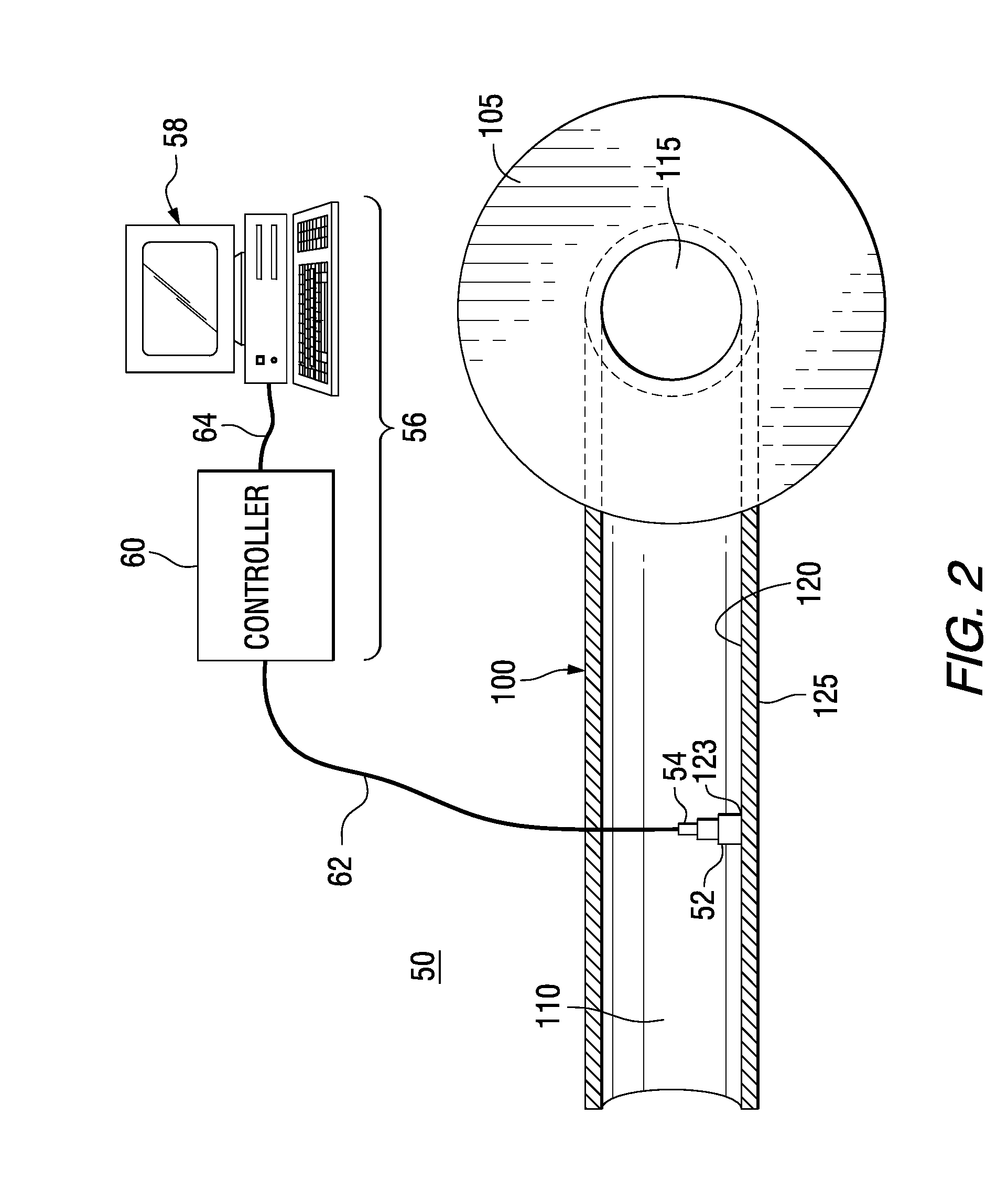
[0038]For this example, an area of the bore 110 of rotor 100 having a width of about 3 inches (7.62 centimeters) is to be examined. To inspect this area using known ultrasonic testing techniques could require about six different wedges (not shown), whereas the same area can be inspected using a single wedge 52 in accordance with the exemplary embodiment of the phased array ultrasonic testing system 50 as shown in FIG. 2. Known 1D techniques are limited in their ability to steer the beam over a relatively large area and therefore, multiple wedges are required. Specifically, as previously discussed, one-dimensional transducers can only steer in one direction which makes it difficult to control the beam as desired when the wedge and transducer are mounted on a curved surface that is not completely flat. The various transducer mounting surfaces on the interior surface of the turbine rotor bore (which is typically a cylindrical body) are curved surfaces and are not flat. Therefore, the a...


PUM


Abstract

A phased array ultrasonic testing system for examining discontinuities in turbine or generator rotor bores formed within turbine or generator rotors of a turbine or generator rotor assembly. The system includes a phased array ultrasonic transducer structured to be coupled to a surface of the rotor bore at a first location in order to emit an ultrasonic beam toward a second location of the rotor bore which is to be examined. The system further includes a control system with a computer and a controller for programming, emitting, and steering the ultrasonic beam via at least one, two-dimensional phased array transducer, thereby precisely and accurately inspecting the area of interest. Computer control of the beam permits the number of inspection locations and the number of different transducer wedges to be reduced providing for an efficient, timely inspection.

Description

FIELD OF THE INVENTION[0001]The present invention generally relates to ultrasonic, non-destructive testing, and more particularly, to a phased array ultrasonic testing system and method for inspecting and / or examining power generation equipment and other industrial equipment. In particular, the present invention relates to a phased array ultrasonic testing system and method for inspecting and / or examining turbine and generator components, such as turbine and generator rotor bores, for discontinuities.BACKGROUND OF THE INVENTION[0002]It is known in the art to routinely inspect steam turbines and generators used for electrical power generation to detect discontinuities. Rotor bore inspections are performed on power generating equipment, such as turbines and generators. These inspections are typically carried out using a variety of convention methods, such as ultrasonic inspection and eddy current inspection. The ultrasonic inspection is employed to inspect areas that are inside the vo...

Claims


Application Information

Patent Timeline
Patent Type & Authority Applications(United States)
IPC IPC(8): G01M13/00
CPCG01M13/00G01N29/07G01N29/223G01N29/2456G01N2291/2693G01N2291/0289G01N2291/106G01N2291/2636G01N29/262G01N29/22G01N29/24G01N29/26
Inventor METALA, MICHAEL J.ABBASI, WAHEED A.
Owner SIEMENS ENERGY INC
Why Eureka
Try Eureka