
Power management systems and methods for use in an oxygen concentrator

a power management system and oxygen concentrator technology, applied in the field of health equipment, can solve the problems of difficult and impractical ambulatory activities with patients, limited oxygen supply, and inability to meet the needs of patients, and achieve the effect of facilitating gas flow

Active Publication Date: 2012-03-08
INOVA LABS INC
View PDF6 Cites 58 Cited by
  • Summary
  • Abstract
  • Description
  • Claims
  • Application Information

AI Technical Summary

Benefits of technology

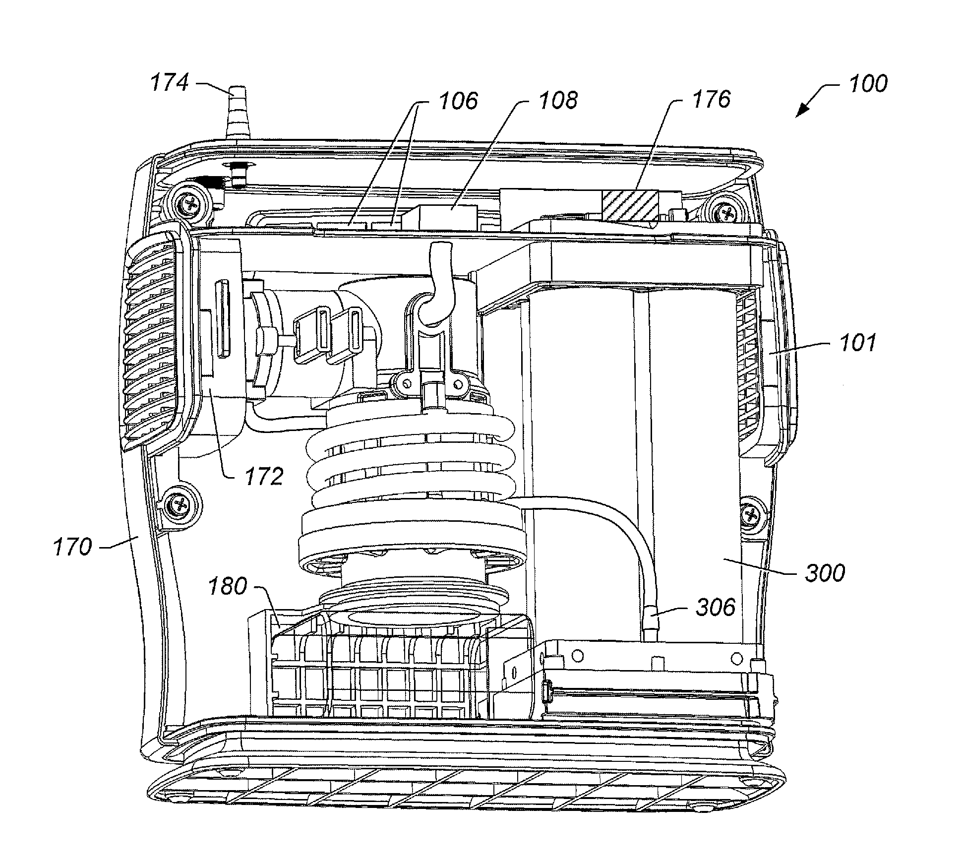
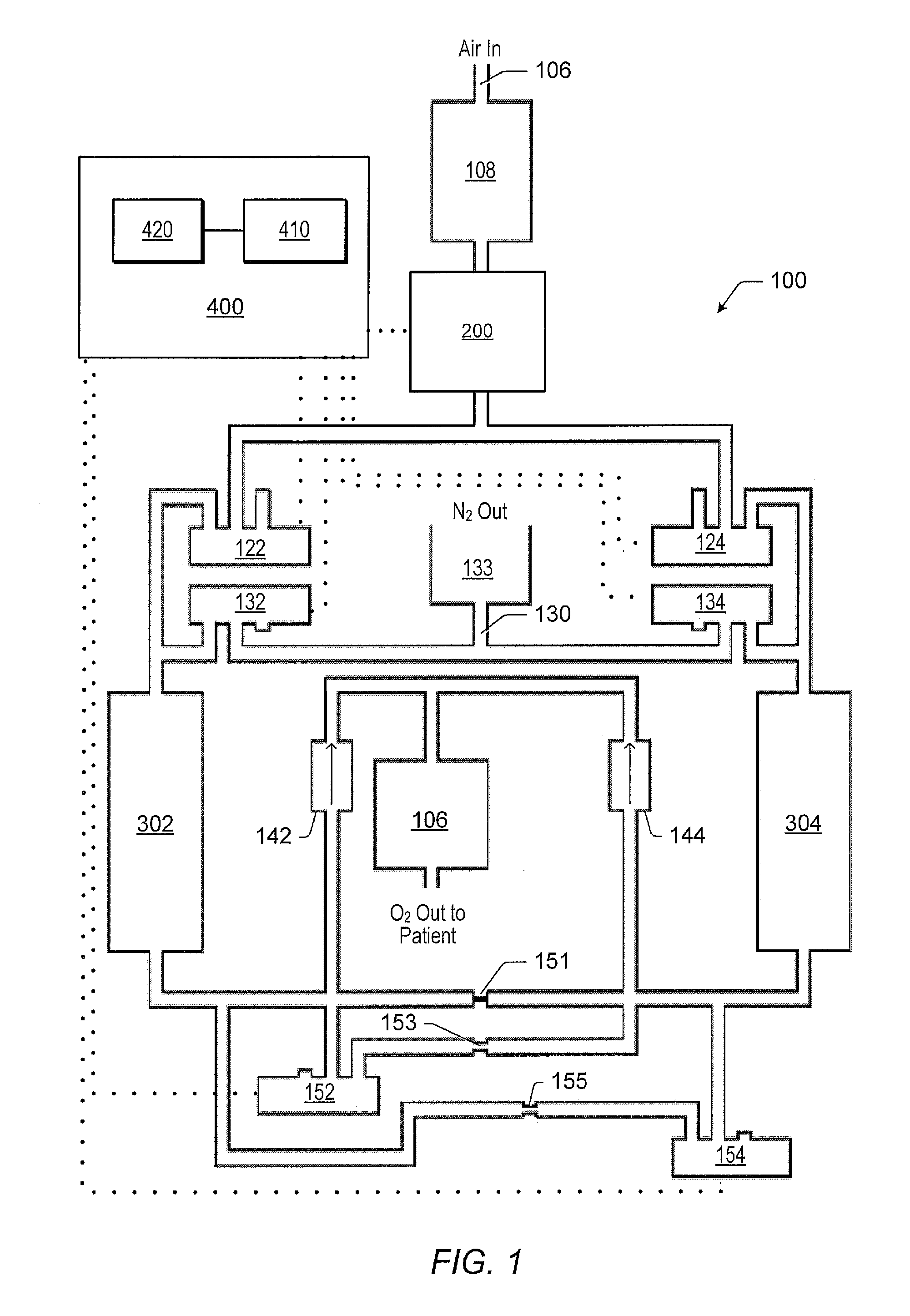
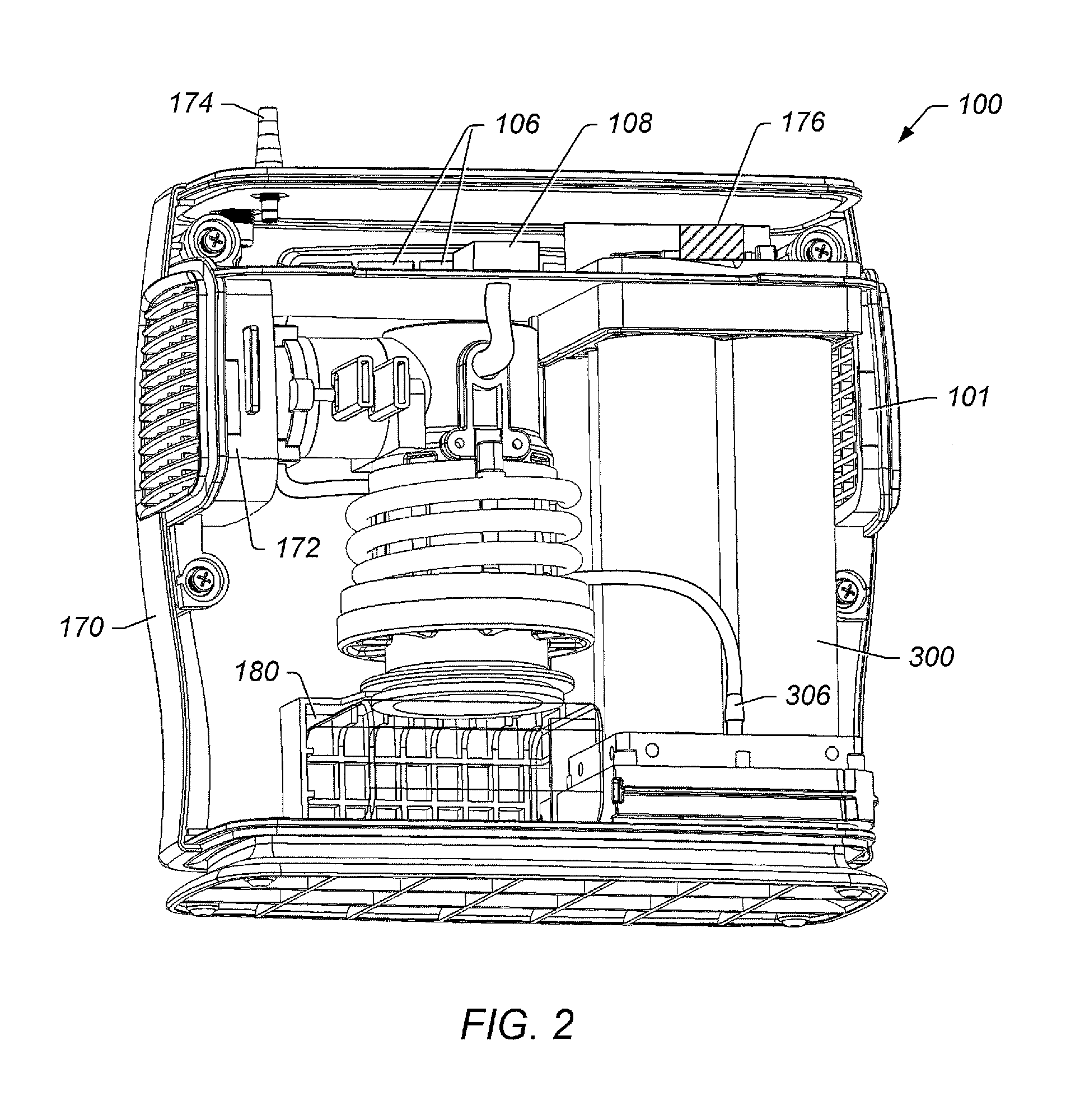
[0012]In an embodiment, an oxygen concentrator apparatus includes at least two canisters; gas separation adsorbent disposed in at least two canisters, wherein the gas separation adsorbent separates at least some nitrogen from air in the canister to produce oxygen enriched gas; and a compression system. The compression system includes a compressor coupled to at least one canister, wherein the compressor compresses air during operation; and a motor coupled to the compressor, wherein the motor drives the operation of the compressor. The oxygen concentrator apparatus also includes a compressor outlet conduit coupling the compressor to at least one canister, wherein compressed air is transferred from the compressor to at least one canister through the compressor outlet conduit. An air transfer device is coupled to the motor, wherein the air transfer device creates an air flow when the motor is operated. At least a portion of the compressor outlet conduit is positioned proximate to at least a portion of the motor. An outlet of one or more canisters is positioned such that gas exiting one or more canisters during a venting process is directed toward at least the portion of the compressor outlet conduit positioned proximate to the motor, and gas exiting one or more canisters during a venting process is directed toward at least a portion of the motor proximate to the compressor outlet conduit, during use. The air transfer device facilitates flow of gas exiting the canister during the venting process.

Problems solved by technology

Most stationary forms of exercise like tread mills and stationary bicycles, however, are too strenuous for these patients.
The disadvantage of these tanks is that they have a finite amount of oxygen and they are heavy, weighing about 50 pounds, when mounted on a cart with dolly wheels.
Traditional oxygen concentrators used to provide these flow rates have been bulky and heavy making ordinary ambulatory activities with them difficult and impractical.

Method used


Image

  • Power management systems and methods for use in an oxygen concentrator
  • Power management systems and methods for use in an oxygen concentrator
  • Power management systems and methods for use in an oxygen concentrator

Examples


Embodiment Construction

[0054]It is to be understood the present invention is not limited to particular devices or methods, which may, of course, vary. It is also to be understood that the terminology used herein is for the purpose of describing particular embodiments only, and is not intended to be limiting. Headings are for organizational purposes only and are not meant to be used to limit or interpret the description or claims. As used in this specification and the appended claims, the singular forms “a”, “an”, and “the” include singular and plural referents unless the content clearly dictates otherwise. Furthermore, the word “may” is used throughout this application in a permissive sense (i.e., having the potential to, being able to), not in a mandatory sense (i.e., must). The term “include,” and derivations thereof, mean“including, but not limited to.”

[0055]The term “coupled” as used herein means either a direct connection or an indirect connection (e.g., one or more intervening connections) between o...


PUM


Abstract

Described herein are various embodiments of an oxygen concentrator system In some embodiment, an oxygen concentrator system includes improved charging and battery control circuits.

Description

BACKGROUND OF THE INVENTION[0001]1. Field of the Invention[0002]The present invention relates generally to health equipment and, more specifically, to oxygen concentrators.[0003]2. Description of the Related Art[0004]There are many patients that require supplemental oxygen as part of Long Term Oxygen Therapy, LTOT. Currently, the vast majority of patients that are receiving LTOT, are diagnosed under the general category of Chronic Obstructive Pulmonary Disease, COPD. This general diagnosis includes such common diseases as Chronic Asthma, Emphysema, Congestive Heart Failure and several other cardio-pulmonary conditions. Other people (e.g., obese individuals) may also require supplemental oxygen, for example, to maintain elevated activity levels.[0005]Doctors may prescribe oxygen concentrators or portable tanks of medical oxygen for these patients. Usually a specific oxygen flow rate is prescribed (e.g., 1 liter per minute (LPM), 2 LPM, 3 LPM, etc.). Experts in this field have also re...

Claims


Application Information

Patent Timeline
Patent Type & Authority Applications(United States)
IPC IPC(8): B01D53/02
CPCA61M16/0683A61M16/101A61M2016/0021A61M2016/0027A61M2016/0039A61M2205/3358B01D53/0446B01D53/047B01D2256/12B01D2257/102B01D2259/402B01D2259/4533B01D2259/4541C01B13/0259A61M16/0063A61M16/0677A61M16/12A61M16/107A61M16/0858
Inventor WILKINSON, WILLIAM R.WESTERSTEN, ALLAN STENHASSAN, ALAA
Owner INOVA LABS INC
Learn More