Speed governor of engine

a technology of speed governor and engine, which is applied in the direction of speed sensing governor, machine/engine, mechanical apparatus, etc., can solve the problems of difficult to provide the speed governor on the crankshaft, and the speed governor cannot be provided on the cam shaft, so as to achieve sufficient centrifugal force, reduce the size of the crankcase, and reduce the effect of the speed governor

Active Publication Date: 2012-03-08
KAWASAKI MOTORS LTD
View PDF6 Cites 16 Cited by
  • Summary
  • Abstract
  • Description
  • Claims
  • Application Information

AI Technical Summary

Benefits of technology

[0012](1) According to the present invention, an attachment mechanism and a drive mechanism of the speed governor are formed by utilizing the existing balancer shaft, the drive gear for balancer and the driven gear for balancer. Thus, there is no need for newly providing a governor shaft, a drive gear, and a driven gear exclusive to the speed governor, and the number of parts for the speed governor can be reduced and size of the crankcase can be decreased.
[0013](2) With the above configuration (a), the support pins for the flyweights are arranged in the recess portion of the driven gear. Thus, in comparison to a structure in which boss portions for supporting the flyweights are formed on an end surface of the gear as in the conventional example, a projecting amount of the flyweights from the end surface of the driven gear is reduced, so that size of the speed governor can be decreased. A long distance from the support pins to gravity centers of the flyweights can be ensured, and sufficient centrifugal force can be generated. Thus, size of the flyweights themselves can be decreased.
[0014](3) Since the recess portion for attaching the support pins is formed into an annular shape, the recess portion can be cut at the same time as a lathing work of the driven gear, so that a working process can be reduced. The recess portion is formed on the entire periphery of the end surface of the driven gear. Thus, a thickness reducing effect can be obtained, so that weight of the driven gear can be reduced.
[0015](4) According to the above configuration (b), the driven gear, the flyweights, and the like can be attached to the balancer shaft before attaching the crankcase cover to the crankcase. Thus, the crankcase cover can be attached in a state that the driven gear is not provided on the side of the crankcase cover. That is, at the time of attaching the crankcase cover, the crankcase cover can be attached in a state that the driven gear, the flyweights, and the like on the balancer shaft can be visually recognized, so that an assembling task of the speed governor is easily performed.

Problems solved by technology

However, there is a case where a speed governor cannot be provided on the cam shaft due to various devices installed in the cam shaft or a shape of the cam shaft itself.
Thus, in terms of a space or a structure, it is difficult to provide the speed governor on the crankshaft.

Method used


Image

  • Speed governor of engine
  • Speed governor of engine
  • Speed governor of engine

Examples


first embodiment

of the Invention

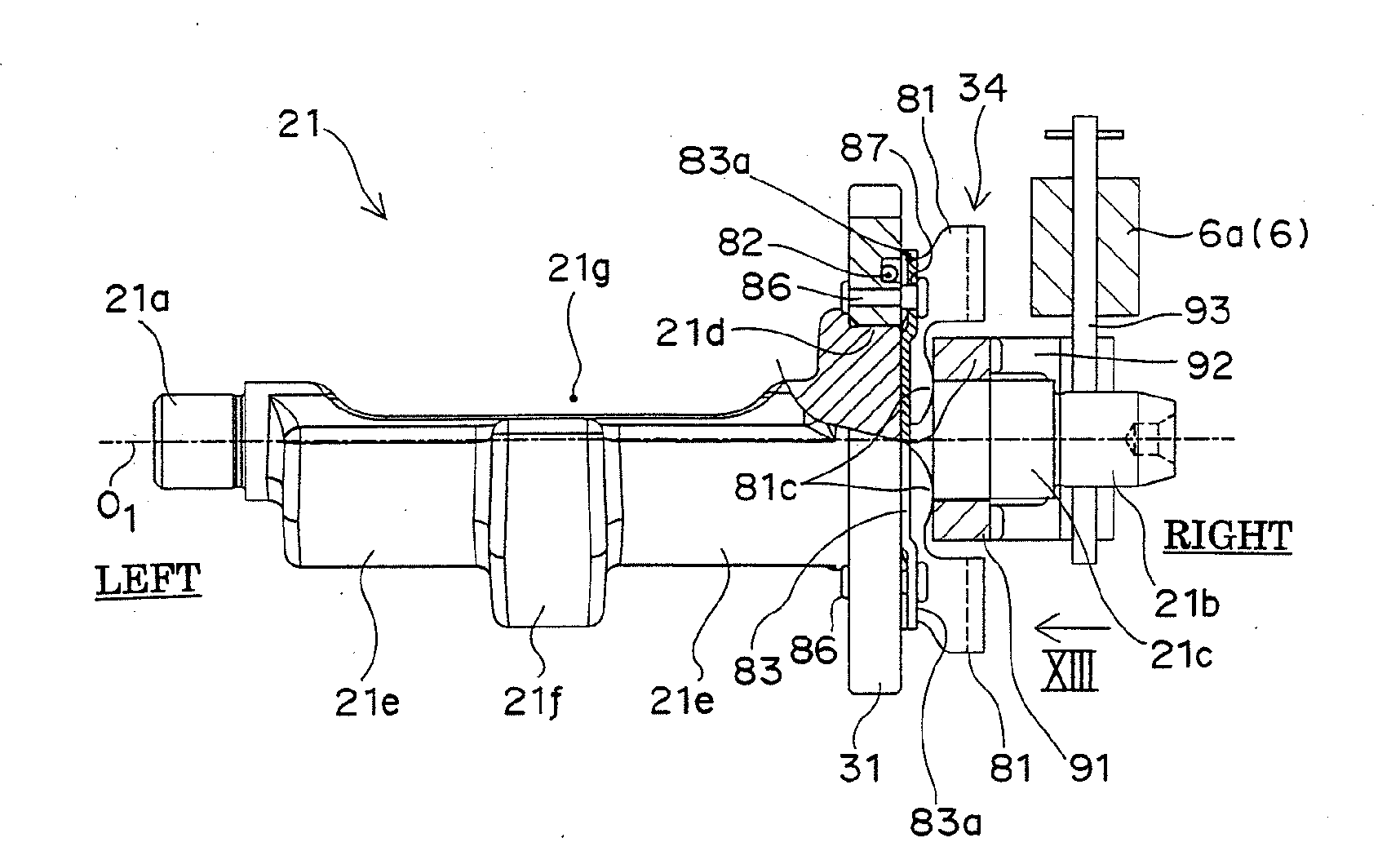
[0038]FIGS. 1 to 17 show an engine with an inclined cylinder according to a first embodiment of the present invention. The embodiment of the present invention will be described based on these figures.

(Configuration of Entire Engine)

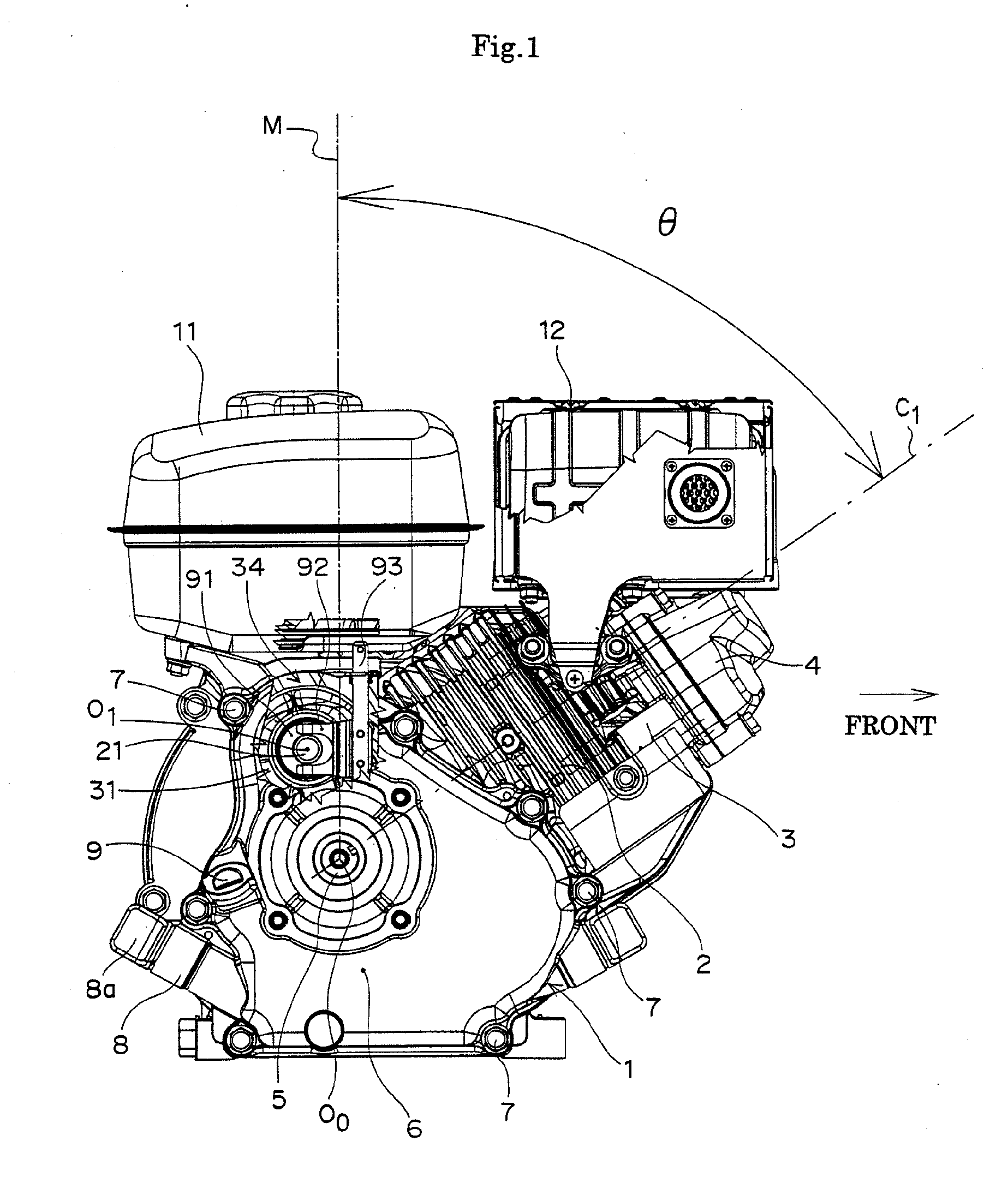
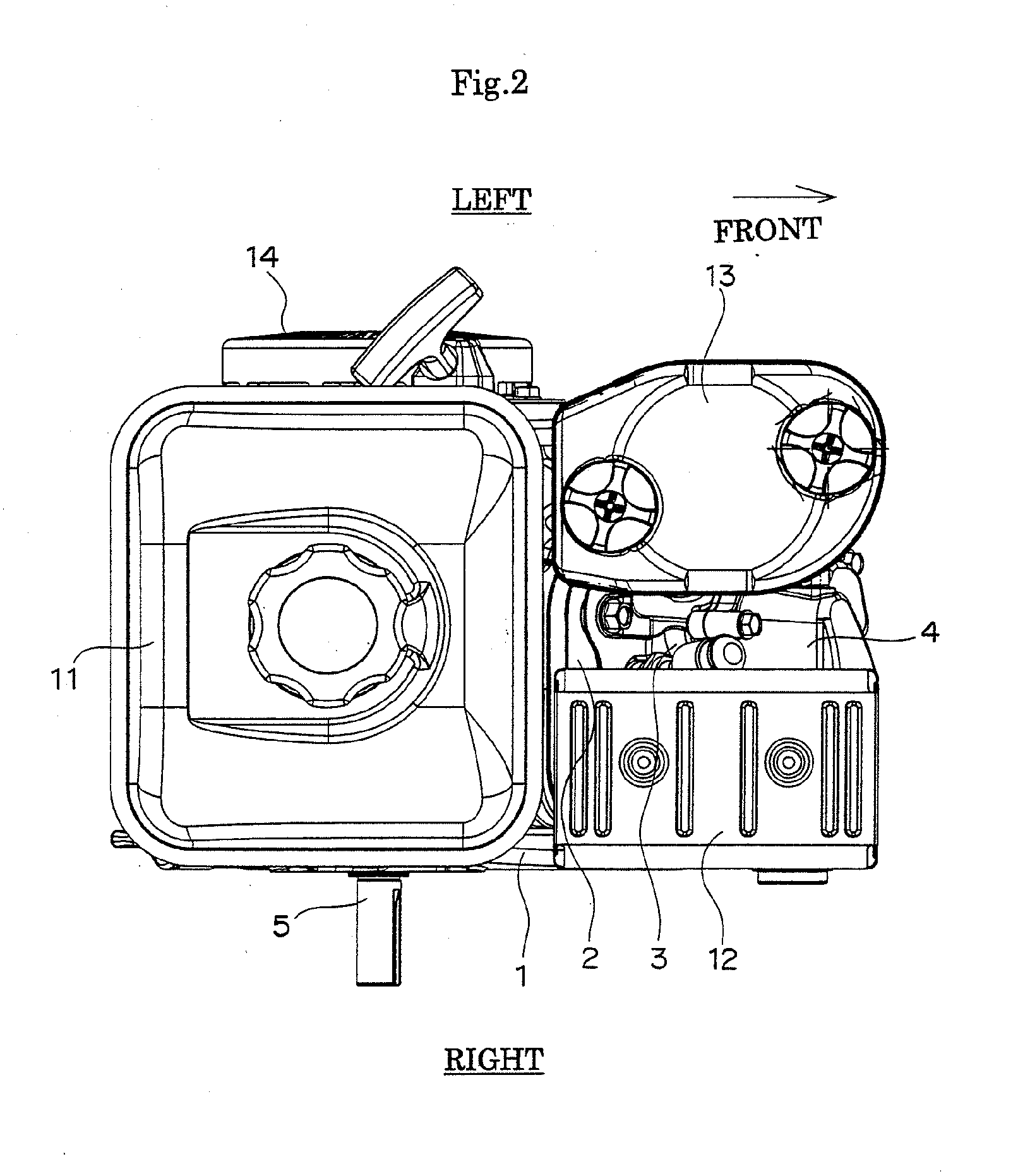
[0039]FIG. 1 is a side view in which the engine with the inclined cylinder is seen in the axial direction of a crankshaft 5. For convenience of description, the side toward which a cylinder 2 is inclined in the horizontal direction orthogonal to the substantially horizontal crankshaft 5 is regarded as the “front side”, and the axial direction of the crankshaft 5 seen from the rear side of the engine is regarded as the “lateral direction (right and left direction)” of the engine.

[0040]In FIG. 1, the cylinder 2 is formed on an upper surface in a front half part of a crankcase 1 integrally with the crankcase 1, and a cylinder head 3 and a head cover 4 are successively fastened to the cylinder 2. A center line C1 of the cylinder 2 is inclined ...


PUM


Abstract

The present invention is to provide a speed governor of an engine having a crankshaft and a balancer shaft arranged substantially in parallel to the crankshaft, in which a drive gear provided in the crankshaft and a driven gear provided in the balancer shaft are meshed with each other so as to transmit mechanical power, the speed governor including a plurality of flyweights pivotally supported on the driven gear of the balancer shaft via a plurality of support pins, and an interlock mechanism for connecting the plurality of flyweights to a fuel feed portion for feeding fuel to a combustion chamber of the engine.

Description

BACKGROUND OF THE INVENTION[0001]1. Field of the Invention[0002]The present invention relates to a speed governor of an engine, particularly to a mechanical type speed governor provided with flyweights.[0003]2. Description of the Prior Art[0004]In a mechanical type speed governor of an engine, a plural of flyweights is opened or moved outward in the radial direction by centrifugal force, whereby a throttle opening position or an amount of fuel can be controlled. As a support structure of the flyweight, for example, there is a conventional structure in which the flyweight is pivotally supported on a gear provided on a cam shaft via a support pin or the like. According to this structure, there is no need for newly providing a governor shaft and governor drive gears. However, there is a case where a speed governor cannot be provided on the cam shaft due to various devices installed in the cam shaft or a shape of the cam shaft itself.[0005]In an utility engine for agriculture described ...

Claims


Application Information

Patent Timeline
Patent Type & Authority Applications(United States)
IPC IPC(8): F02D31/00
CPCF02D9/02F02D31/00F16F15/265F02M69/18F02D2009/0203
Inventor YANO, TAKAHIROHIRANO, MICHIO
Owner KAWASAKI MOTORS LTD
Why Eureka
Try Eureka