
Portable remote racking device for a circuit breaker

a circuit breaker and remote racking technology, which is applied in the direction of air-break switches, high-tension/heavy-dress switches, electrical apparatus, etc., can solve the problems of large circuit breakers, heavy weight and bulk, and prevent the mechanical linkage of the cradle mechanism inside the switchgear, and prevent the damage of the cradle mechanism. inside the switchgear, the effect of overcoming inertia

Active Publication Date: 2012-03-08
SCHNEIDER ELECTRIC USA INC
View PDF8 Cites 27 Cited by
  • Summary
  • Abstract
  • Description
  • Claims
  • Application Information

AI Technical Summary

Benefits of technology

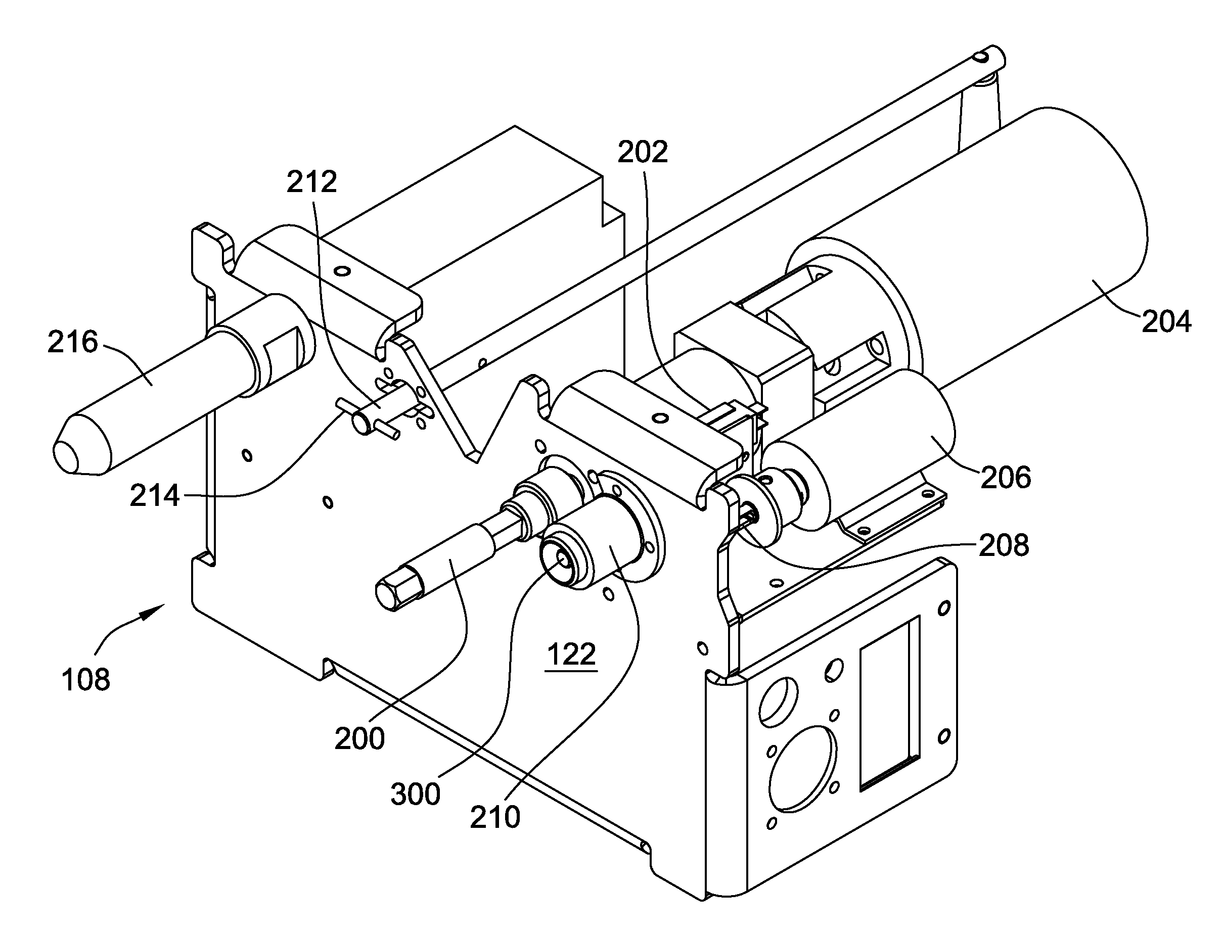
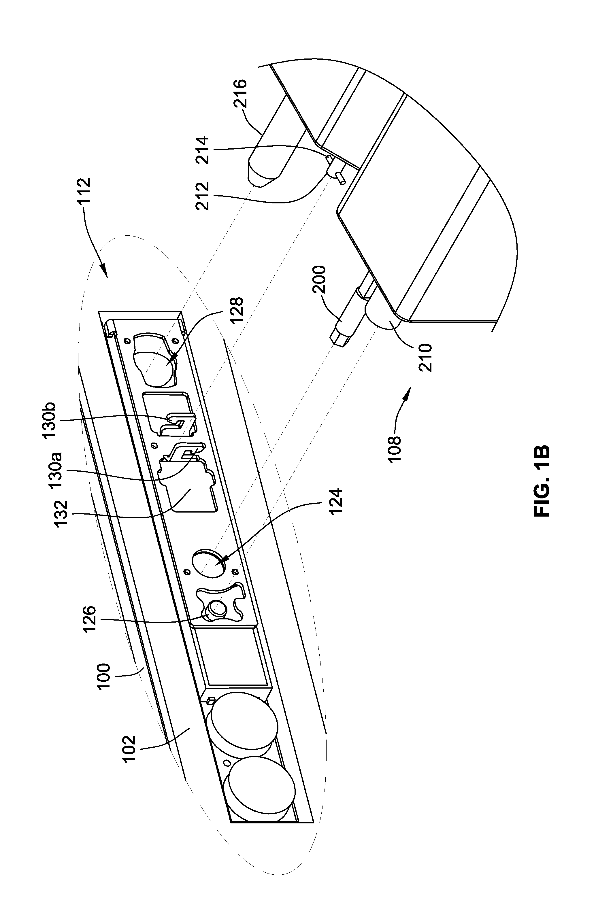
[0006]To initiate a racking operation, the operator depresses a button or switch on the remote control device that causes the actuator pin to depress the button arm of the cradle mechanism, thereby simulating the manual action by the operator who would normally use a finger to depress the button arm. Then, the operator pushes another button or switch on the remote control device to start a racking operation. A signal is sent over the electrical cable to the remote racking device, which begins to turn the motor in a direction indicated by the operator via the remote control device. The motor turns the drive, which cranks the cradle mechanism, causing the circuit breaker to rack in or out of the switchgear. When the mechanism inside the cradle reaches the next stopping position, the button arm pops out, which pushes the actuator pin in the remote racking device back into the remote racking device, engaging a switch that sends an input signal to a circuit inside the remote racking device. When the circuit receives this input signal, it produces an output signal in the form of an electrical pulse that causes the motor to stop and briefly reverse itself, bringing the motor and the accompanying circuit breaker to a sudden stop. This prevents the mechanical linkage of the cradle mechanism inside the switchgear from locking up and also prevents damage to the cradle mechanism inside the switchgear. Normally, the motor, which is connected to a heavy load, has an inertia that wants to continue to apply rotational energy even after power is removed. By reversing the motor briefly when the button arm pops out, this inertia can be overcome, effectively slamming the brakes on the motor and the accompanying movement of the circuit breaker.

Problems solved by technology

These circuit breakers are very heavy and bulky, much larger than those typically found in residential homes.

Method used


Image

  • Portable remote racking device for a circuit breaker
  • Portable remote racking device for a circuit breaker
  • Portable remote racking device for a circuit breaker

Examples


Embodiment Construction

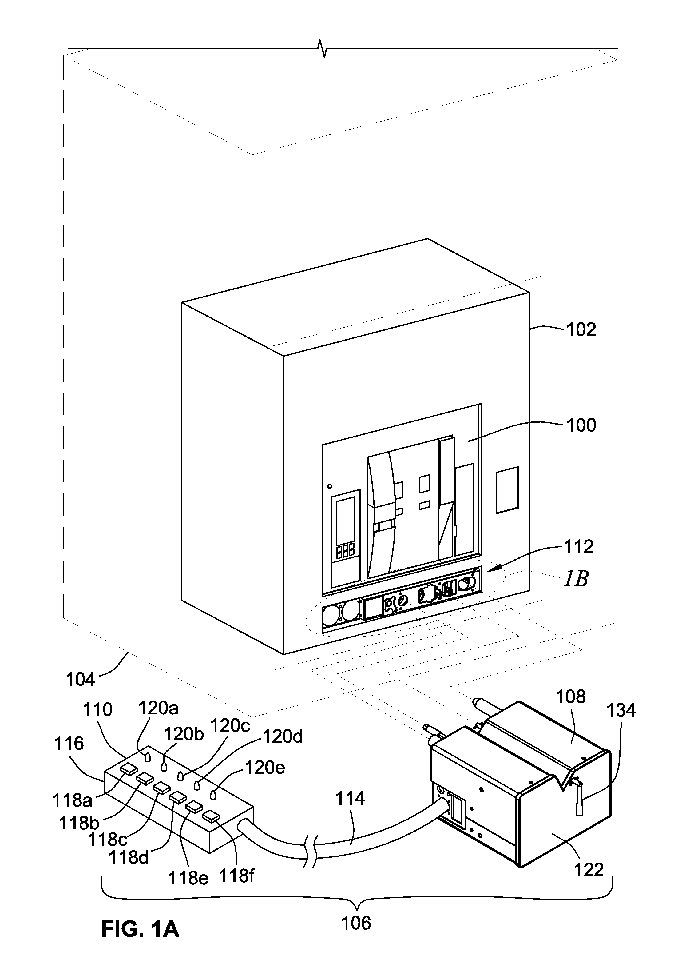
[0021]FIG. 1A is a perspective view of a circuit breaker 100 housed within a cradle or enclosure 102 for use in electrical switchgear equipment (or switchgear / board) 104 and a remote racking system 106. The switchgear / board 104 can have a high, medium, or low voltage rating as defined by the American National Standards Institute (ANSI) or can refer to a “switchboard” as defined in Underwriters Laboratory Standard UL891. The terms switchgear and switchboard are referred to interchangeably and synonymously herein and refer to the same device. A non-limiting example of a suitable circuit breaker 100 for use in connection with aspects of the present disclosure is the MASTERPACT® circuit breaker available from Schneider Electric. The remote racking system 106 includes a portable, remote racking device 108 and a remote control device 110, which is not drawn to scale in FIG. 1A but rather has been enlarged for ease of illustration. The cradle 102 includes a front panel 112 that is accessib...


PUM


Abstract

A portable, remote racking device that is controlled by a remote control. The remote racking device includes a drive that fits into a corresponding crank access hole formed in a front panel of a cradle housing a circuit breaker installed into a switchgear. The drive turns a mechanism inside the cradle that causes the circuit breaker to be racked into or out of the switchgear. The remote racking device includes an actuator pin that abuts a corresponding button arm protruding through the front panel. The remote control includes a control for depressing the button arm and another control for causing a motor to rotate the drive. The actuator pin detects when the button arm pops out of the panel, and a circuit in the remote racking device briefly reverses the motor to bring it and the circuit breaker to a sudden stop, preventing the mechanical linkages of the mechanism from locking-up or becoming damaged and avoiding over-torquing the motor.

Description

FIELD OF THE INVENTION[0001]The present disclosure relates to remote racking systems for electrical switchgear / board equipment, and, more particularly, to a portable remote racking device with a remote control device for racking a circuit breaker into or out of electrical switchgear / board equipment.BACKGROUND[0002]Electrical switchgear / board equipment (sometimes just called switchgear or switchboard) house very large and heavy circuit breakers that protect loads that can consume thousands of amps of current. The procedure for making or breaking the electrical connections inside the electrical equipment between primary current carrying connectors in the circuit breaker and the corresponding connectors in the switchgear is referred to as racking Racking such high-capacity circuit breakers is a procedure wrought with personal danger to the operator's safety. A possibility always exists that an explosion will occur due to a fault creating an arc flash, causing significant injury, includ...

Claims


Application Information

Patent Timeline
IPC IPC(8): H01H33/42H01H9/20
CPCH02B11/127H02B3/00
Inventor ZYLSTRA, HENRY J.PUJARA, JESILVOLESKY, GARY A.DVORAK, ROBERT F.
Owner SCHNEIDER ELECTRIC USA INC
Learn More