Ratchet-type tensioner

a ratchet-type, tensioner technology, applied in the direction of valve drives, machines/engines, gearing, etc., can solve the problems of hydrostatic pressure in the oil chamber 510, breakage of one or more teeth, etc., to prevent excessive biting of the pawl, stable supply of oil, and easy fabrication of passages

Inactive Publication Date: 2010-11-25
TSUBAKIMOTO CHAIN CO
View PDF0 Cites 16 Cited by
  • Summary
  • Abstract
  • Description
  • Claims
  • Application Information

AI Technical Summary

Benefits of technology

[0020]According to another aspect of the invention, the second oil supply passage can formed in the housing in order to introduce oil under pressure from a source external to said housing directly into the pin-receiving hole. The second oil supply passage formed in the housing passage may be disposed at any desired position irrespective of the location of the first oil supply passage. Accordingly, the length of the second oil passage can be made short, and the passage can be fabricated easily.
[0021]In another embodiment, the second oil supply passage is formed in the housing in such a way as to deliver oil from the high-pressure oil chamber directly into the pin-receiving hole. In this embodiment, the pin operates the pawl in synchronism with pulsations in the pressure of the oil in the high pressure oil chamber. Accordingly, the pawl is immediately disengaged from the rack teeth on the plunger on start-up of the engine, permitting smooth protruding and retracting movement of the plunger.
[0022]In still another embodiment, the second oil supply passage is provided with an orifice for absorbing pulsation in oil supplied to the pin-receiving hole through the second oil supply passage. The orifice controls the amount of oil introduced into the pin-receiving hole when the supply of oil is excessive. The orifice also controls leakage of oil from the pin-receiving hole when the supply of oil is insufficient. Accordingly, the orifice enables the tensioner to absorb pulsations generated in oil supplied by an oil pump, and also ensures a stable supply of oil to the pin-receiving hole.
[0023]According to another aspect of the invention, a pin-supporting spring can be provided in the pin-receiving hole for e...

Problems solved by technology

If the engine is inoperative for a long period of time, air can enter the oil chamber 510, and, as a result, the hydraulic pressure in the oil chamber 510, which is influenced by pulsations in the hydraulic pressure generated by an oil pump o...

Method used


Image

  • Ratchet-type tensioner
  • Ratchet-type tensioner
  • Ratchet-type tensioner

Examples


first embodiment

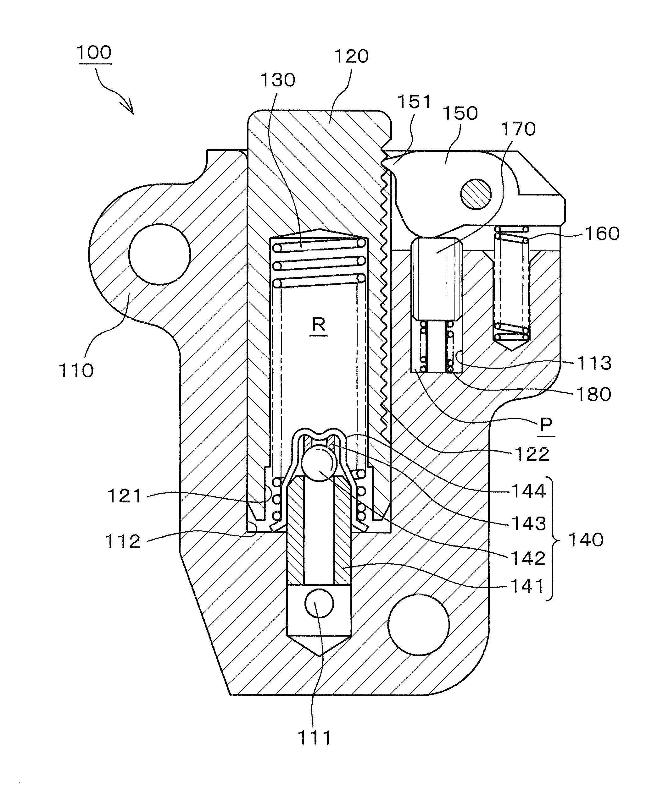
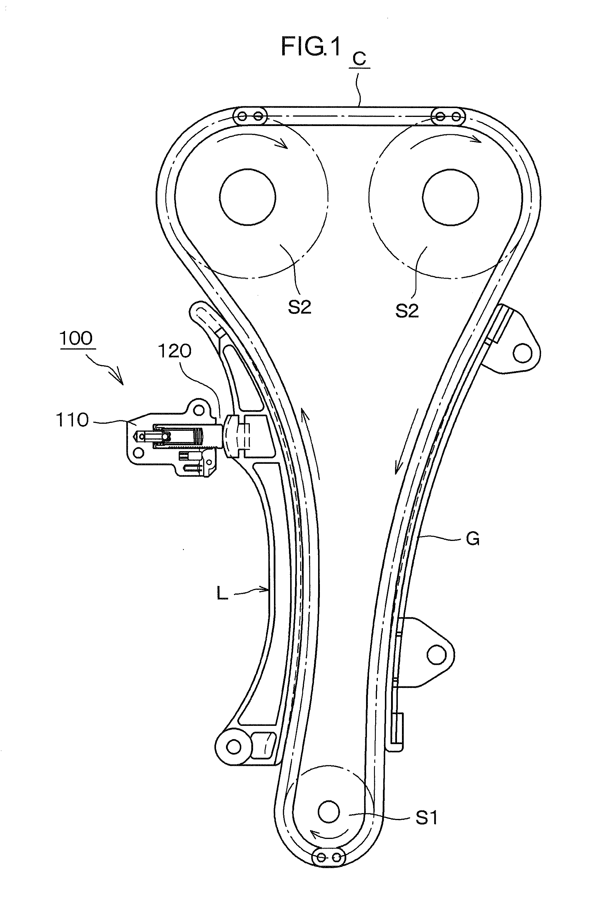
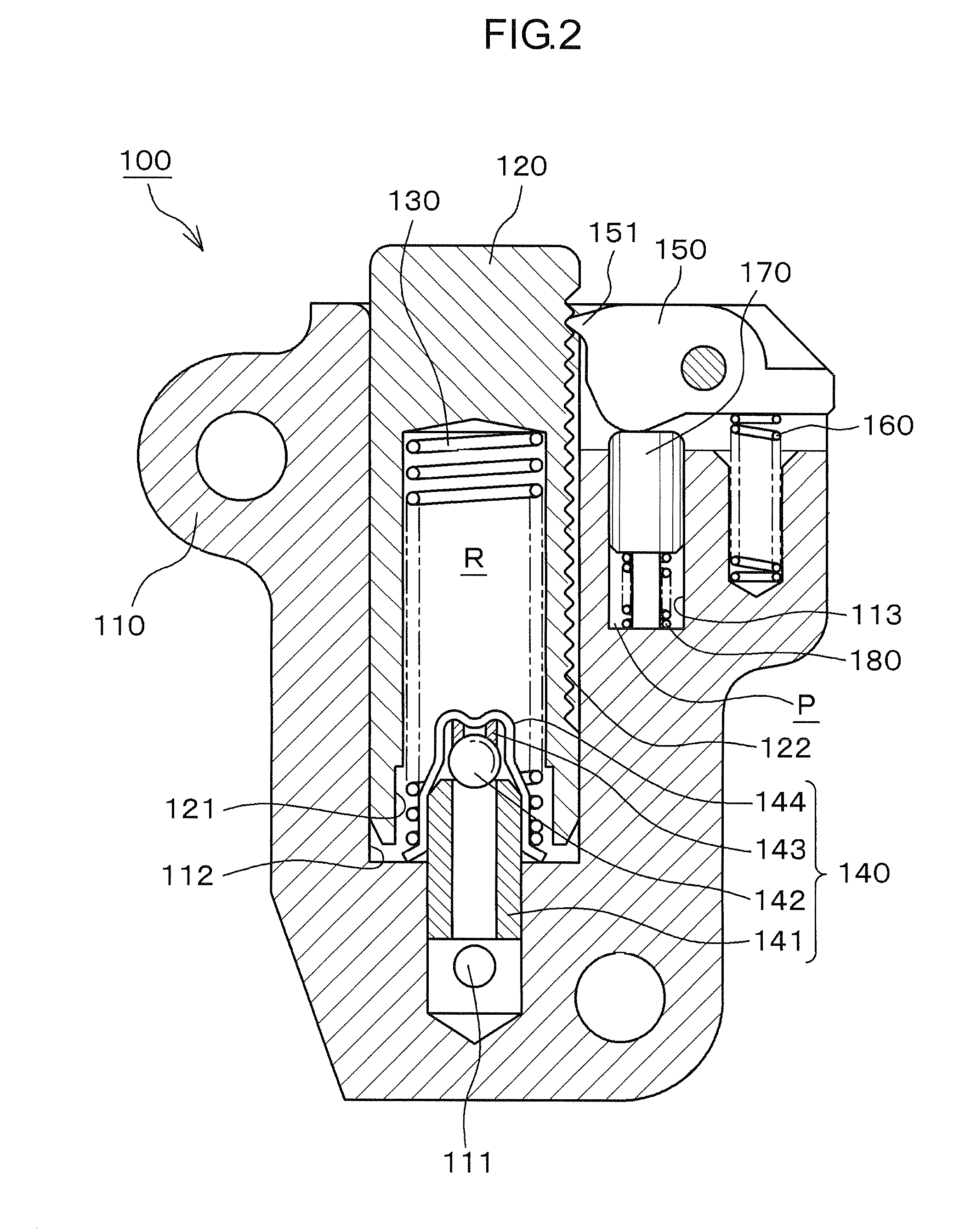
[0038]As shown in FIG. 1, a ratchet-type tensioner 100 according to the invention is attached to an engine body adjacent the slack side of a timing chain C, i.e. the span of the chain that travels from a driving sprocket S1 on the engine crankshaft toward one of two driven sprockets S2 on the engine camshafts. A plunger 120, protruding from the tensioner housing 110 moves in and out of the housing to apply tension to the slack side of the timing chain C through a pivoted lever L by pressing the back of the lever at a location spaced from lever's pivot axis.

[0039]The tension side of the chain, i.e., the span traveling toward the crankshaft sprocket S1 from a camshaft sprocket S2, slides on, and is guided by, a stationary chain guide G fixed on the engine body. Arrows in FIG. 1 show the direction of rotation of the sprockets and the direction of movement of the chain.

[0040]As shown in FIG. 2, a first oil supply passage 111 is provided in the tensioner housing for introducing oil suppl...

second embodiment

[0054]the ratchet-type tensioner is tensioner 200, shown in FIG. 6. This tensioner is used in the same manner as the ratchet-type tensioner 100 described above, but is different in that it is provided with an orifice 290 for absorbing pulsations in the oil supplied under pressure from the engine block. Except for the orifice and the extension of the length of the pin-receiving hole in order to accommodate the orifice, the structure is substantially the same as that of the tensioner 100 described above. Accordingly, parts of the ratchet-type tensioner 200 shown in FIG. 6 that are identical with, or correspond to, those of the ratchet-type tensioner 100 are denoted by reference numerals exceeding by 100, the corresponding reference numerals in FIG. 2.

[0055]The orifice 290 controls the amount of the oil under pressure introduced into chamber P of the pin-receiving hole through the second oil supply passage 214, when the amount of supplied oil is excessive. The orifice 290 also controls...

third embodiment

[0057]the ratchet-type tensioner is tensioner 300, shown in FIG. 7. This tensioner is used in the same manner as the ratchet-type tensioner 100 described above, but is different in the disposition and configuration of the second oil supply passage 314 for introducing oil into the chamber P of the pin-receiving hole. In other respects, the structure of tensioner 300 is the same with that of tensioner 100 described above. Accordingly, parts of the ratchet-type tensioner 300 shown in FIG. 7 that are identical with, or correspond to, those of the ratchet-type tensioner 100 are denoted by reference numerals exceeding by 200, the corresponding reference numerals in FIG. 2.

[0058]The second oil supply passage 314, for introducing oil into the oil chamber P of pin-receiving hole 312, is formed in the housing 310 and communicates directly with the high pressure oil chamber R at a location near the bottom of the plunger-accommodating hole 312. The passage 314 is connected to high pressure oil ...


PUM


Abstract

In a ratchet-type tensioner, a rocking ratchet pawl is released from a rack of teeth on a tensioner plunger following engine start-up by a hydraulically operated pin slidable in a pin hole and caused to protrude therefrom by oil under pressure received directly from an external oil supply, or alternatively from the tensioner's high pressure oil chamber through a passage in the tensioner housing. Optionally, an orifice can be provided within the pin hole to control flow of oil when the supply is excessive and to avoid leakage when the supply is insufficient.

Description

CROSS REFERENCE TO RELATED APPLICATIONS[0001]This application claims priority under Title 35, United States Code, §119 (a)-(d) based on Japanese Patent Application No. 2009-121767, filed May 20, 2009. The disclosure of Japanese Patent Application No. 2009-121767 is incorporated by reference in its entirety.FIELD OF THE INVENTION[0002]The invention relates to a ratchet-type tensioner for applying tension to the timing chain which drives a camshaft, and optionally other components, of an engine.BACKGROUND OF THE INVENTION[0003]It is known to apply tension to a timing chain by means of a tensioner having a plunger slidable in a plunger-accommodating hole in a tensioner housing. The plunger and housing cooperate to form an oil chamber, and the plunger is urged in a direction to exert tensioning force on the timing chain by a plunger-biasing spring and also by hydraulic pressure applied from an external pressure source to the oil in the oil chamber.[0004]FIG. 9 shows a tensioner describe...

Claims


Application Information

Patent Timeline
IPC IPC(8): F16H7/08
CPCF01L1/02F01L1/022F16H7/0848F16H2007/0893F16H2007/0812F16H2007/0853F16H2007/0859F16H2007/0806
Inventor HIRAYAMA, MANABUMATSUSHITA, TAKAHIRONAKAKUBO, KATSUYAKUREMATSU, YUJIYOSHIDA, OSAMUYOSHIMOTO, SHINTAROU
Owner TSUBAKIMOTO CHAIN CO
Why Eureka
Try Eureka