Hydraulic control apparatus and hydraulic control method

a technology of hydraulic control apparatus and hydraulic servo unit, which is applied in the direction of servomotors, gearing, machines/engines, etc., can solve the problems of not being able to control the speed ratio, the operation of the servo mechanism in one direction cannot be stopped, and the supply to one of the ports cannot be stopped, so as to prevent the servo mechanism

Inactive Publication Date: 2006-08-10
TOYOTA JIDOSHA KK
View PDF3 Cites 16 Cited by
  • Summary
  • Abstract
  • Description
  • Claims
  • Application Information

AI Technical Summary

Benefits of technology

[0007] It is an object of the invention to provide an improved hydraulic control apparatus and method capable ...

Problems solved by technology

In the structure where the 4-port type servo valve serves to control operations of the servo mechanism, when a sticking or the like occurs in the servo valve and as a result, the oil supply to one of the ports cannot be sto...

Method used


Image

  • Hydraulic control apparatus and hydraulic control method
  • Hydraulic control apparatus and hydraulic control method
  • Hydraulic control apparatus and hydraulic control method

Examples


Embodiment Construction

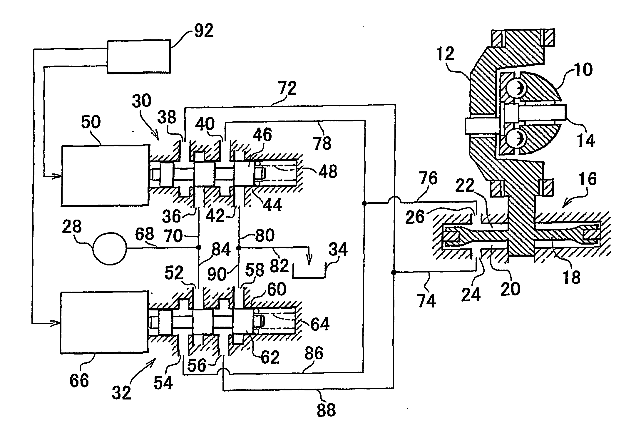
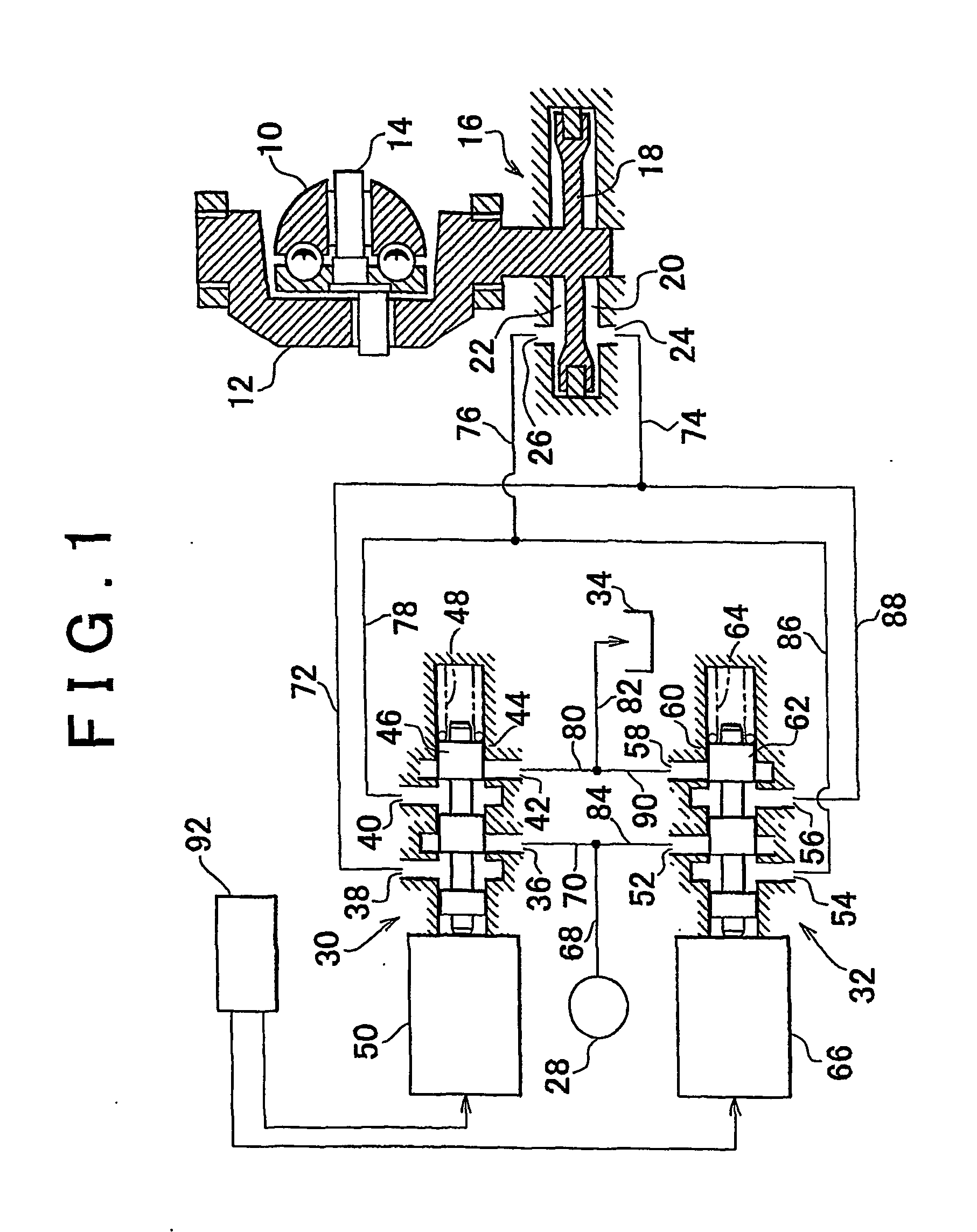
[0028]FIG. 1 schematically shows an embodiment of the invention applied to a hydraulic control apparatus for controlling a toroidal type continuously variable transmission. Referring to FIG. 1, a power roller 10 in a known toroidal type continuously variable transmission (hereinafter referred to as CVT) is supported by a trunnion 12 via an eccentric shaft 14, and interposed between a pair of discs (not shown). A speed ratio of a rotating power transferred between the pair of discs can be varied by changing a tilted angle of the power roller 10 with respect to the discs. The tilted angle of the power roller 10 with respect to the discs is changed by a hydraulic actuator 16 that temporarily displaces the trunnion 12 in a vertical direction.

[0029] So long as a center axis of the power roller 10 intersects with a center axis of the disc, the force of the disc at a drive side applied to the power roller 10 acts in parallel to the tilted axis of the power roller 10 at a contact point bet...


PUM


Abstract

A hydraulic control apparatus includes two oil flow control valves (30, 32) each provided with a supply control portion (36, 38, 52, 54) for controlling an oil supply from a pressurized oil source, and a discharge control portion (40, 42, 56, 58) for controlling connection with a discharge passage. One of those oil flow control valves supplies/discharges oil to/from one of hydraulic chambers (22, 24) that are oppositely formed in a hydraulic servo mechanism. An operation direction of the hydraulic servo mechanism is performed by operating one of the oil flow control valves. The other operation direction of the hydraulic servo mechansim is performed by operating the other oil flow control valve.

Description

BACKGROUND OF THE INVENTION [0001] 1. Field of Invention [0002] The invention relates to a hydraulic control apparatus and method, and more particularly, to a hydraulic control apparatus and method for a hydraulic servo unit in which an operation direction is selected to a first direction when oil is supplied from a first port and discharged from a second port, and to a second direction opposite to the first direction when the oil is supplied from the second port and discharged from the first port. [0003] 2. Description of Related Art [0004] The servo mechanism having a first port and a second port is structured to select its operation direction to a first direction when oil is supplied from the first port and discharged from the second port, and to a second direction opposite to the first direction when the oil is supplied from the second port and discharged from the first port. The above structured servo mechanism is well known as being employed for various types of machines in an...

Claims


Application Information

Patent Timeline
IPC IPC(8): F15B13/04B60W10/04B60W10/06B60W10/10B60W10/101B60W10/109F02D29/00F15B20/00F16H61/00F16H61/12F16H61/66F16H61/662F16H61/664F16H63/50
CPCF15B20/008F16H61/12F16H61/6648F15B20/00F16H61/66
Inventor IWASE, YUJISUGAYA, MASAMINISHIZAWA, HIROYUKIHAYAKAWA, KISABUROOSAWA, MASATAKA
Owner TOYOTA JIDOSHA KK
Why Eureka
Try Eureka