Reinforcing bar binding machine

a technology of reinforcing bars and binding machines, which is applied in the direction of bundling machines, bundling articles, and other domestic articles, etc., can solve the problems of deteriorating mechanical performance such as torque, rotation number and so on, affecting the operation of the machine, and remarkably dropping the supply voltage. , to achieve the effect of stable operation

Active Publication Date: 2015-04-14
MAX CO LTD
View PDF14 Cites 16 Cited by
  • Summary
  • Abstract
  • Description
  • Claims
  • Application Information

AI Technical Summary

Benefits of technology

[0010]One or more embodiments of the invention provide a reinforcing bar binding machine in which operation is stable even under low temperature environment.
[0013]In the operation of the reinforcing bar binding machine, it is during the binding wire twisting step that the heaviest load is applied and the drop of the voltage is the largest. Therefore, by detecting and comparing the power supply voltage only during the binding wire twisting step, an object of the invention can be achieved and a control routine is simplified.
[0014]In the reinforcing bar binding machine in one or more embodiments of the invention, the power supply voltage during the operation is monitored, and twisting operation is suspended before the voltage drops below the CPU operation voltage, whereby the binding wire twisting mechanism is returned to the initial position. Therefore, it is possible to prevent the binding wire twisting mechanism from being stopped while grasping the binding wire when the CPU stops, and useless troubles such as cutting and unwinding the binding wire which is grasped by the twisting mechanism are not required.

Problems solved by technology

A battery driven tool, not confined to the reinforcing bar binding machine, has a problem that mechanical performance such as torque, rotation number and so on may be deteriorated due to deterioration of battery performance under low temperature environment.
However, because heavy load is applied in the twisting step for twisting a metallic wire, a power supply voltage remarkably drops, and when discharging performance of the battery is deteriorated under the low temperature environment, the power supply voltage instantaneously drops below an operation voltage of the CPU during the twisting step, and the machine sometimes stops during the twisting operation.
By repeating the stop and reset of the CPU in this manner, one cycle of the operation becomes unable to be completed.
Therefore, there is such anxiety that stops of operation may frequently occur due to a drop of the voltage under low temperature environment.

Method used


Image

  • Reinforcing bar binding machine
  • Reinforcing bar binding machine
  • Reinforcing bar binding machine

Examples


Embodiment Construction

[0044]Now, referring to the drawings, an exemplary embodiment of the invention will be described.

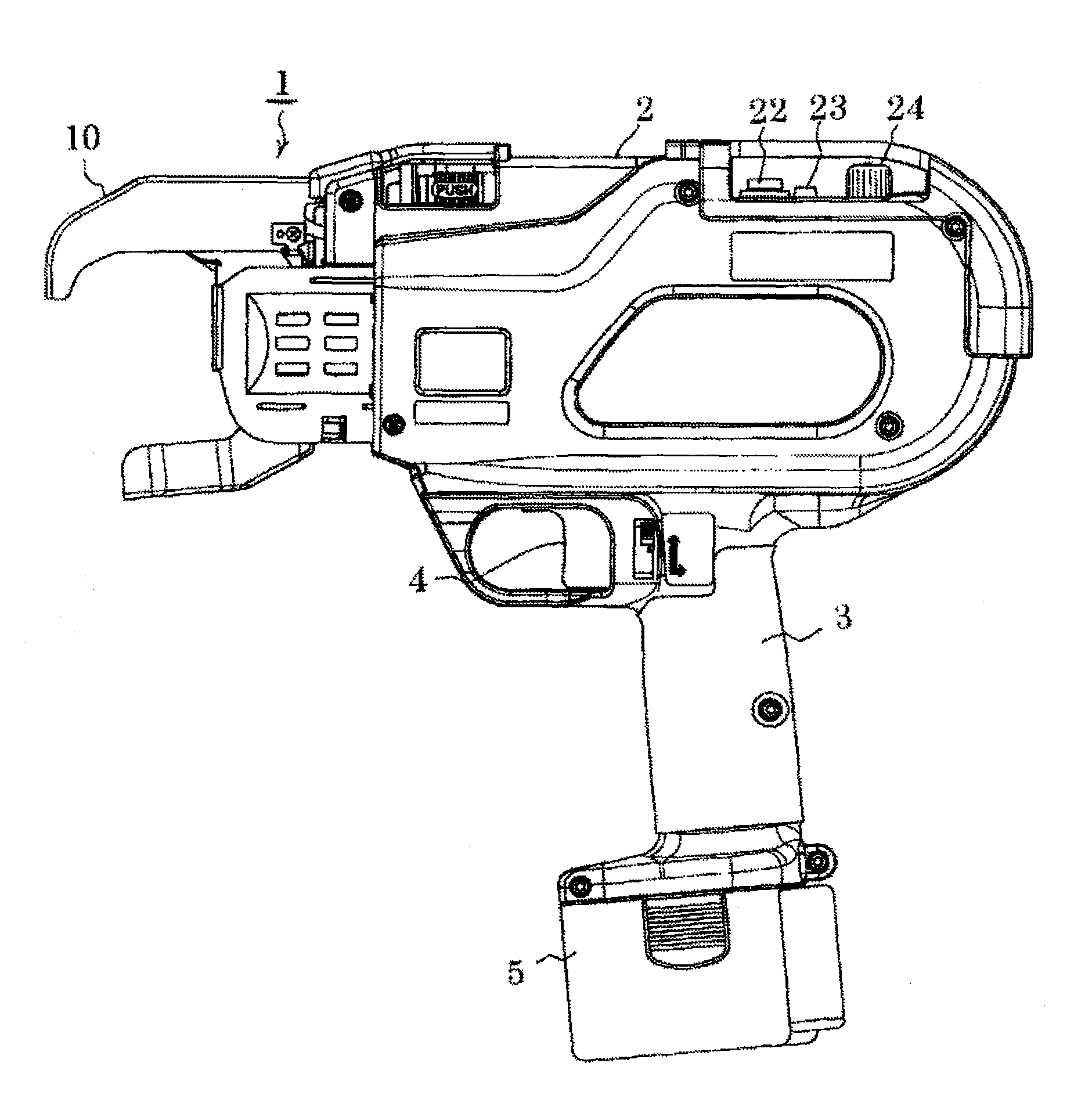
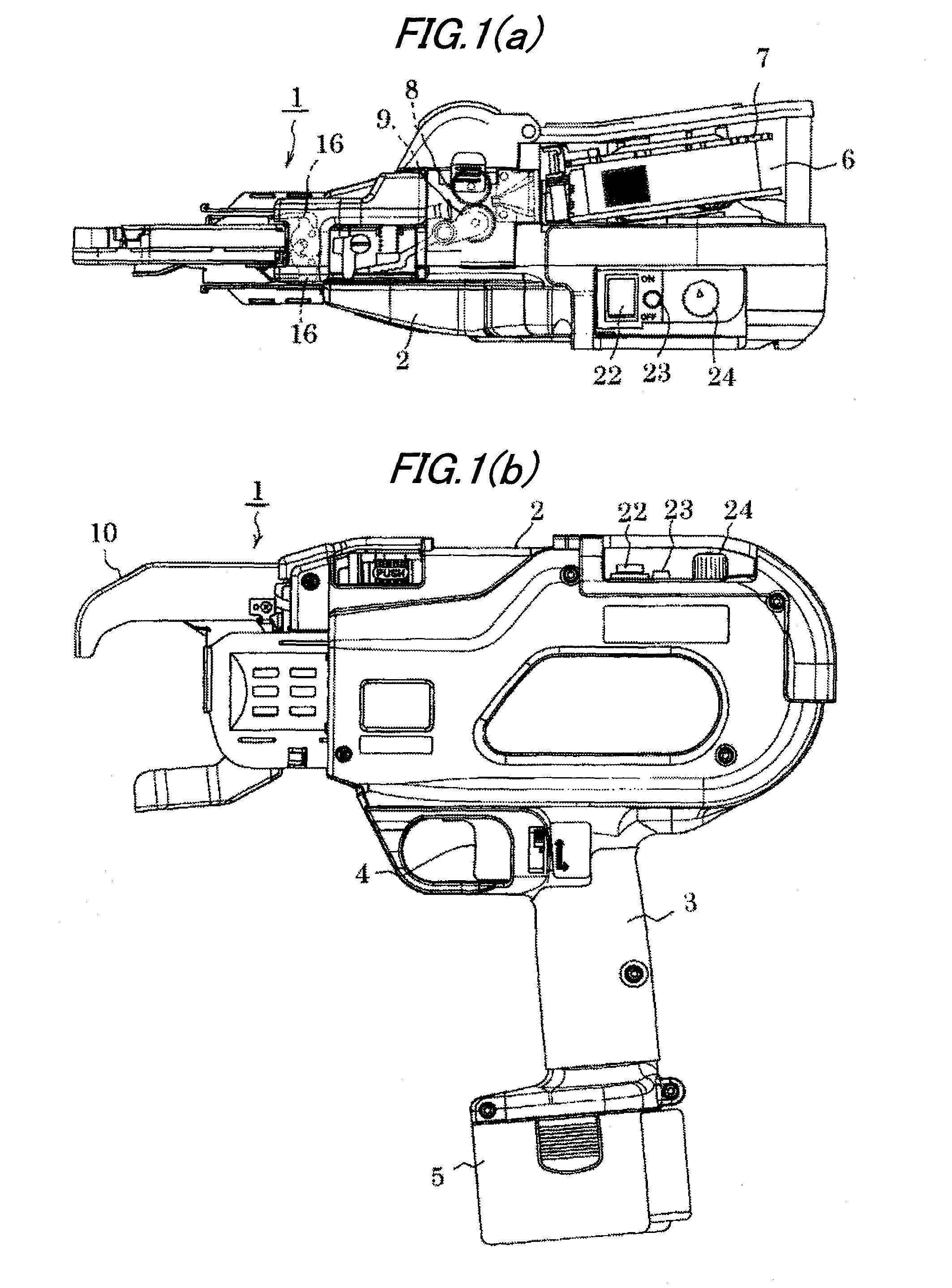
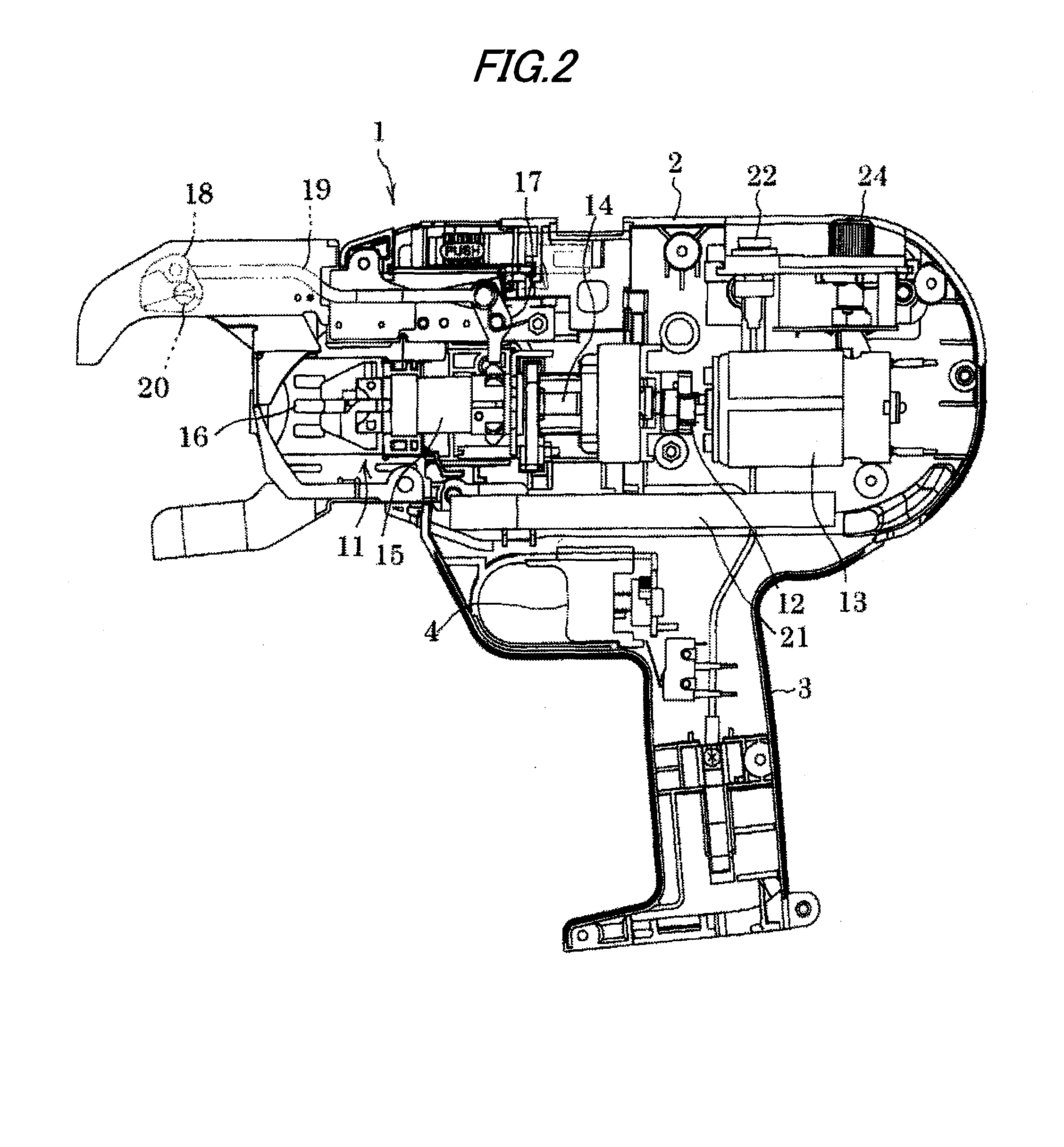
[0045]In FIGS. 1(a), 1(b), and FIG. 2, a reinforcing bar binding machine 1 is shown. In the reinforcing bar binding machine 1 which has the same mechanical structure as the conventional machine, a grip 3 is extended downward from an outer casing 2, a trigger lever 4 is provided on a front face of a base part of the grip 3, and a rechargeable battery pack 5 is mounted on a lower end of the grip 3.

[0046]As shown in FIG. 1(a), a binding wire reel containing room 6 is provided on a side face of a rear part of the outer casing 2, and a binding wire of a binding wire reel 7 which is loaded in this room 6 is clamped by a binding wire feeding mechanism including a main gear 8 with a V-shaped groove and a driven gear 9 with a V-shaped groove to be fed forward. Then, the binding wire moves forward while being curved along an inner peripheral face of a curved guide nose 10 which is provided on a fr...


PUM

PropertyMeasurementUnit
voltageaaaaaaaaaa
currentaaaaaaaaaa
electric currentaaaaaaaaaa

Abstract

A reinforcing bar binding machine is provided with a device for detecting a power supply voltage during a binding wire twisting step subjected to the heaviest load and comparing the power supply voltage with a predetermined CPU operation voltage, and a control device for driving a motor in a reverse direction when the voltage has dropped below the predetermined CPU operation voltage. The power supply voltage during operation is monitored, and twisting operation is suspended before the voltage drops below the CPU operation voltage, whereby the binding wire twisting mechanism is returned to the initial position. Therefore, it is possible to prevent the binding wire twisting mechanism from being stopped while grasping the binding wire, when the CPU stops.

Description

TECHNICAL FIELD[0001]The present invention relates to a reinforcing bar binding machine, and more particularly, to the reinforcing bar binding machine in which improvement in stability of performance under low temperatures and a drop of voltage is achieved.BACKGROUND ART[0002]A reinforcing bar binding machine which is driven by a motor is provided with a binding wire feeding mechanism for feeding a binding wire to wind it around a reinforcing bar, a binding wire twisting mechanism for grasping and twisting the binding wire wound around the reinforcing bar thereby to strongly tighten the reinforcing bar, and a binding wire cutting mechanism for cutting off a back end of a loop of the binding wire from a following binding wire at the same time when twisting operation of the twisting mechanism starts. In the reinforcing bar binding machine, when an operator pulls a trigger lever, one cycle of operation which includes feeding, cutting and twisting the binding wire is carried out. Struct...

Claims


Application Information

Patent Timeline
Patent Type & Authority Patents(United States)
IPC IPC(8): B21F15/04B65B13/28E04G21/12
CPCE04G21/122E04G21/123B65B13/18B65B13/28E04G21/12
Inventor KASAHARA, AKIRAMATSUOKA, ATSUSHI
Owner MAX CO LTD
Why Eureka
Try Eureka