Forward Flow, High Access Consumables for a Plasma Arc Cutting Torch

a plasma arc cutting torch and consumable technology, applied in the direction of manufacturing tools, soldering devices, auxilary welding devices, etc., can solve the problems of premature insufficient cooling of plasma arc torch and overheating and melting of consumable parts, and inefficient cooling. , to achieve the effect of prolonging the life of the consumable, and reducing the cost of production

Active Publication Date: 2012-03-08
HYPERTHERM INC
View PDF12 Cites 41 Cited by
  • Summary
  • Abstract
  • Description
  • Claims
  • Application Information

AI Technical Summary

Problems solved by technology

However, having longer consumables can result in insufficient cooling of the plasma arc torch and the overheating and melting of the consumable parts.
The further away the cooling mechanism is from the heat source, the more inefficient the cooling becomes.
As a result, the extended consumables overheat and melt prematurely.

Method used


Image

  • Forward Flow, High Access Consumables for a Plasma Arc Cutting Torch
  • Forward Flow, High Access Consumables for a Plasma Arc Cutting Torch
  • Forward Flow, High Access Consumables for a Plasma Arc Cutting Torch

Examples


Embodiment Construction

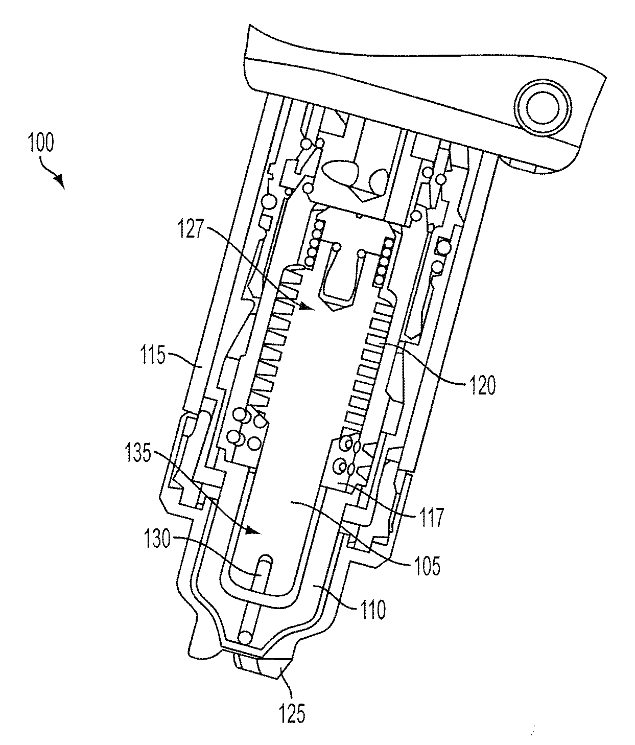
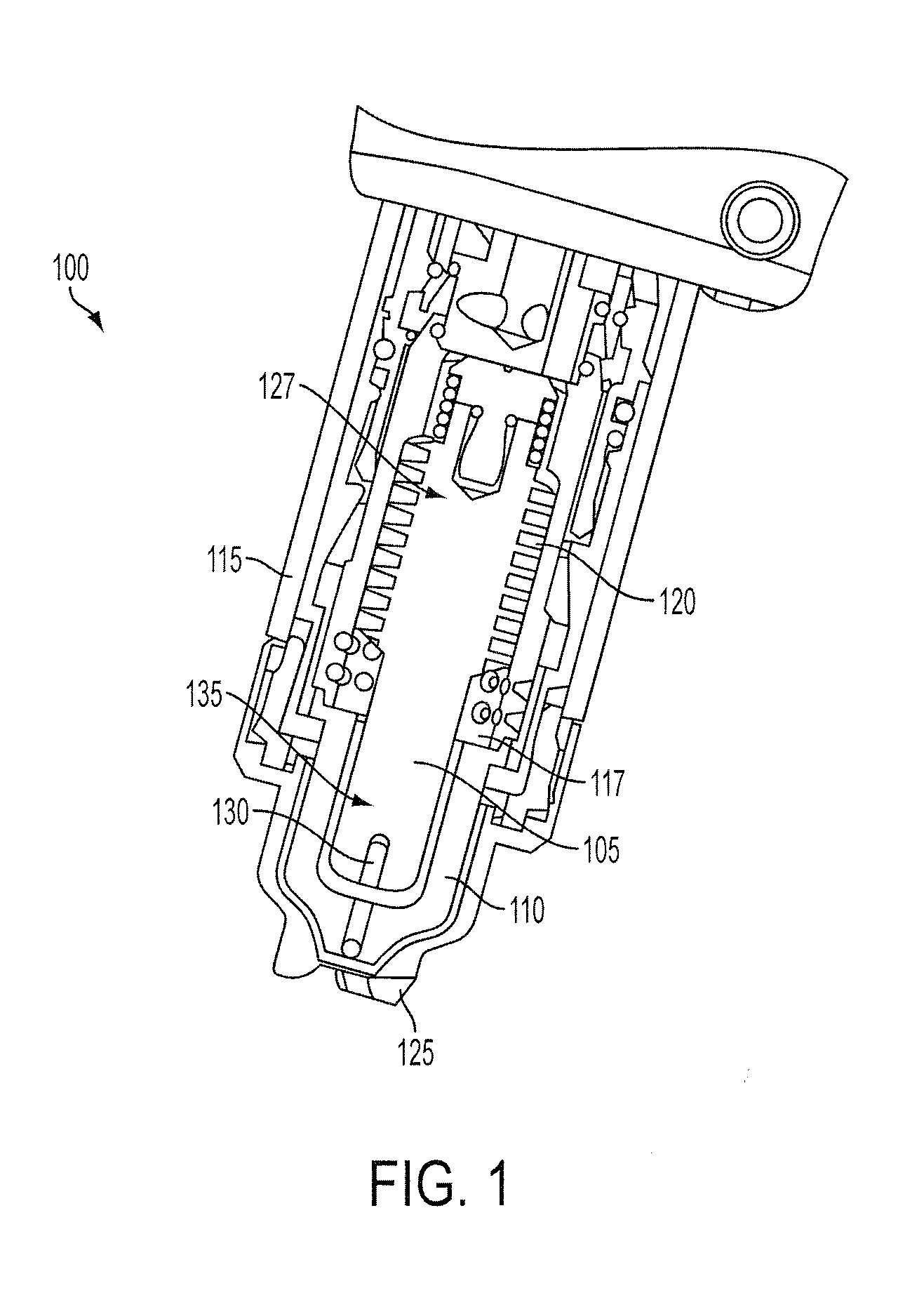
[0056]FIG. 1 shows a cross-sectional view of a plasma arc torch 100. A plasma torch tip is comprised of a variety of different consumables, for example, an electrode 105, a nozzle 110, a retaining cap 115, a swirl ring 117, or a shield 125. The nozzle 110 has a central exit orifice mounted within a torch body. The torch and torch tip can include electrical connections, passages for cooling, and passages for arc control fluids (e.g., plasma gas). The shield 125 can be used to prevent molten spatter from damaging the other components of the torch, for example, the electrode 105, nozzle 110, retaining cap 115, or swirl ring 120. The electrode 105 can include a heat exchanger 120 at a proximal end 127 of the electrode 105.

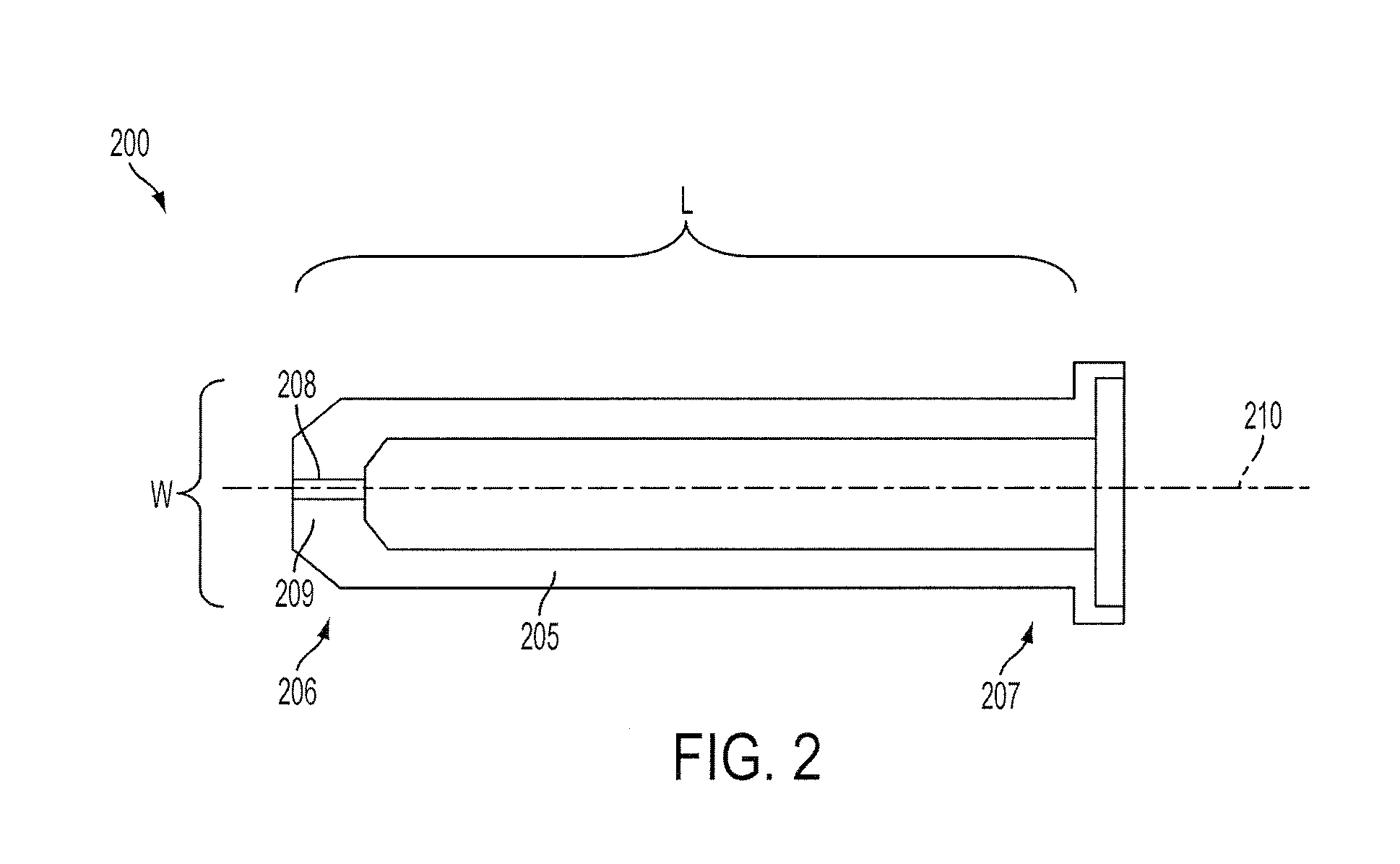
[0057]A plasma arc torch that is capable of reaching into hard to access areas (e.g., channels or corners) can have consumables that are elongated to provide the added reach required to access these types of locations. These longer length consumables (e.g., “pointy” co...


PUM

PropertyMeasurementUnit
lengthaaaaaaaaaa
lengthaaaaaaaaaa
lengthaaaaaaaaaa

Abstract

A nozzle for a plasma arc cutting torch includes a substantially hollow, elongated body capable of receiving an electrode. The nozzle body defines a longitudinal axis and has a length along the axis from a first end of the nozzle body to a second end of the nozzle body. The nozzle also includes a plasma exit orifice disposed at the first end of the body. The first end of the nozzle body has a width and a ratio of the length of the nozzle body to the width of the nozzle body is greater than about 3.

Description

RELATED APPLICATIONS[0001]This application is a continuation-in-part of U.S. patent application Ser. No. 12 / 878,512, filed Sep. 9, 2010, the entire disclosure of which is hereby incorporated herein by reference. This application is a continuation-in-part of U.S. patent application Ser. No. 13 / 169,534, filed Jun. 27, 2011, which is a continuation of U.S. patent application Ser. No. 11 / 611,625, filed Dec. 15, 2006, now U.S. Pat. No. 7,989,727, which claims benefit of and priority to U.S. Provisional Patent Application No. 60 / 825,453, filed Sep. 13, 2006, the entire disclosures of each of which are hereby incorporated herein by reference. This application is a continuation-in-part of U.S. patent application Ser. No. 12 / 032,630, filed Feb. 15, 2008, which claims benefit of and priority to U.S. Provisional Patent Application No. 60 / 901,804, filed Feb. 16, 2007, the entire disclosures of which are hereby incorporated herein by reference.TECHNICAL FIELD[0002]The present invention relates t...

Claims


Application Information

Patent Timeline
Patent Type & Authority Applications(United States)
IPC IPC(8): B23K9/28B23K9/24B23K37/00B23K10/00
CPCB23K10/00H05H1/34Y10T29/49002H05H2001/3457H05H2001/3478H05H2001/3442H05H1/3442H05H1/3457H05H1/3478
Inventor SHIPULSKI, E. MICHAELSANDERS, NICHOLAS A.JASON, JAY L.MATHER, JONATHANTWAROG, PETER J.
Owner HYPERTHERM INC
Why Eureka
Try Eureka