
Use of Battery Energy for Power Grid Optimization and Electric Vehicle Charging

a technology of battery energy and optimization, applied in the direction of charging stations, battery/fuel cell control arrangements, transportation and packaging, etc., can solve the problems of battery state estimation accuracy, infancy technology, and lack of real application of technology

Inactive Publication Date: 2012-03-08
CAI ERIC JAMES +2
View PDF4 Cites 32 Cited by
  • Summary
  • Abstract
  • Description
  • Claims
  • Application Information

AI Technical Summary

Problems solved by technology

Although the battery cell chemistry is capable of meeting the grid application requirements in theory, the real application of the technology is still lacking due to reliability concerns of large number of battery cell connections, as well as the limitation of battery state estimation accuracy and cell balancing techniques.
However, the technology is still in its infancy stage due to cost and battery management system technical limitations.
However, given the current grid capacity, it is expected that the vast amount of energy needed from EV Fast charge stations would put significant stress on the existing grid structure and may reduce the grid operating efficiency.
Another challenge is the lack of standards governing DC charge coupler geometry and data exchange protocol between EV battery management system and charging station control system.
There has not been any application of using a large size battery as energy source to power the DC fast charge station, mainly due to cost and battery management system limitations.
Now it is found by the inventors herein that, even though there are existing technologies that can be used to provide grid optimization services using battery stored energy; or to convert grid AC power to DC for EV fast charge services, there has not been any system available that can provide both DC fast charge and grid optimization services at the same time using battery as energy source.

Method used


Image

  • Use of Battery Energy for Power Grid Optimization and Electric Vehicle Charging
  • Use of Battery Energy for Power Grid Optimization and Electric Vehicle Charging

Examples


Embodiment Construction

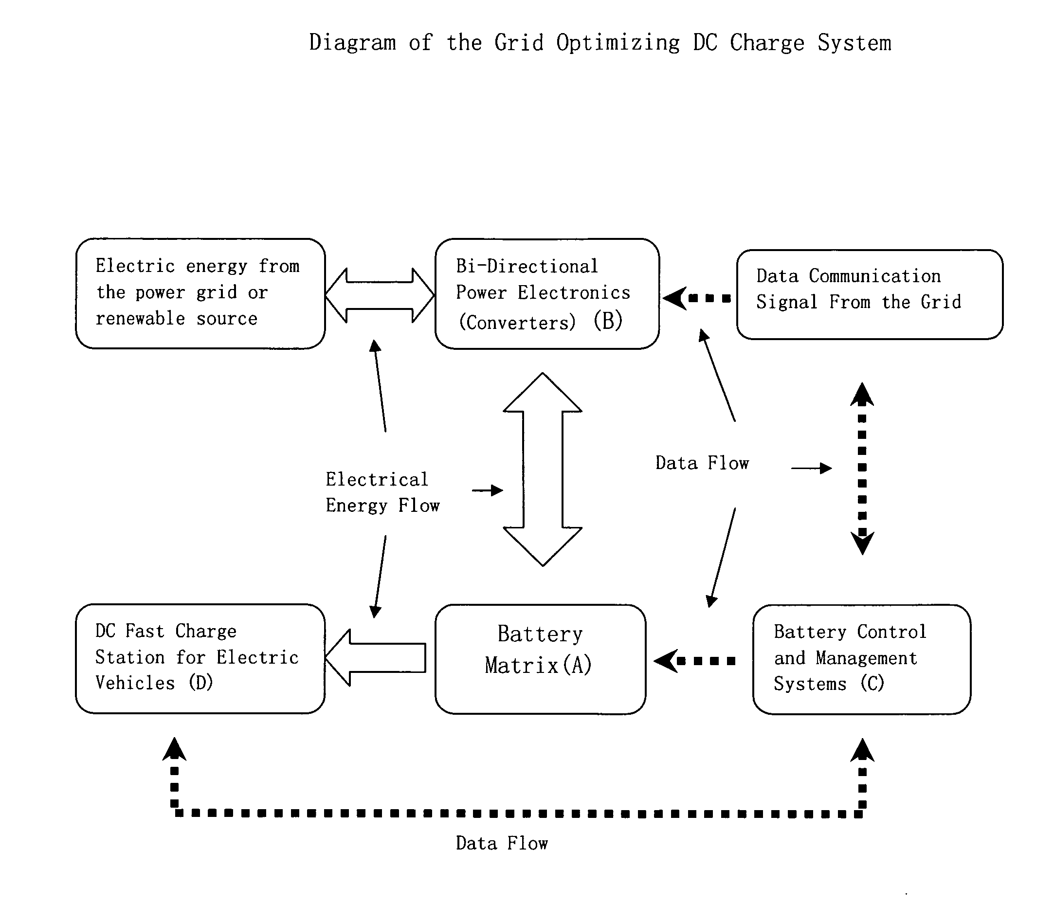
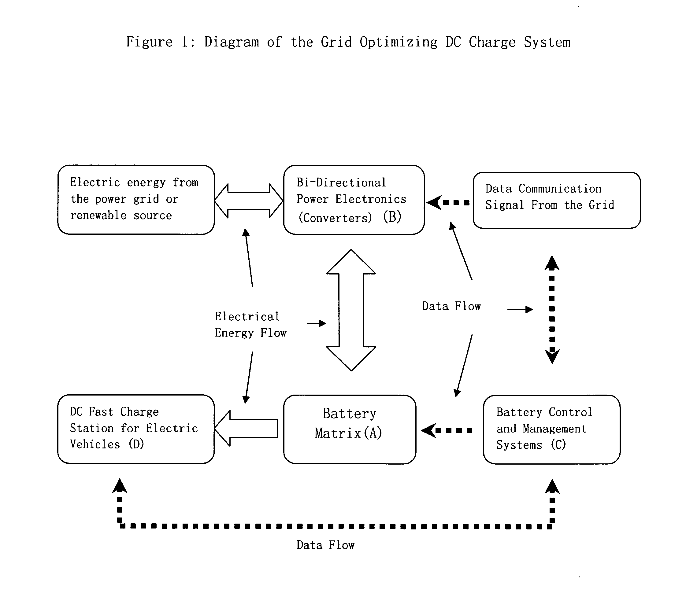
[0011]This invention relates to the concept of a Grid Optimizing Charge System that uses energy stored in battery to provide DC fast charge to electric vehicles while also functions as a grid load leveling energy source and frequency regulating device.

[0012]This Grid Optimizing DC Charge System (GOCS) will use a stationary battery matrix to store energy and will be connected to a high voltage power grid at all time. The charge or discharge of the battery will be controlled by specific algorithms that will enable the power grid to draw electricity from the battery matrix when needed or to charge the battery when the grid load is below certain level. The services that could be provided by this Grid Optimizing Charge System include, but are not limited to:[0013]1. Electric Vehicle Charging—Functioning as a DC to DC charge station to provide electrical energy to electric vehicles[0014]2. Load Shifting / Leveling—Applies a time based load management strategy to charge the battery matrix du...


PUM


Abstract

The use of battery cells to store energy for EV charging and grid optimization and regulation service. The major components of the system and the benefits of such concept are also described.

Description

BACKGROUND OF THE INVENTION[0001]1. Battery Technology[0002]The energy density and cycle life of the Li-ion battery chemistries have improved significantly in the past 10 years. It is projected that by 2015, the cell energy density could pass 200 wh / kg, with room temperature cycle life >5000 cycles at 70% Depth of Discharge or >12000 cycles at 60% Depth of Discharge. We believe that it is reasonable to expect the battery cells used by stationary application to have a full capacity life (100-80% of the original capacity) of 7 years under maximum usage (5 re-charges a day), or 33 years under minimum usage (1 re-charge a day). The reduced capacity life (80-40% of the original capacity) could add another 4-7 years of usage under maximum usage condition.[0003]Although the battery cell chemistry is capable of meeting the grid application requirements in theory, the real application of the technology is still lacking due to reliability concerns of large number of battery cell connect...

Claims


Application Information

Patent Timeline
Patent Type & Authority Applications(United States)
IPC IPC(8): H02J7/00
CPCB60L11/1824Y04S30/14H02J7/0054Y02T10/7005Y02T10/7094Y02T90/14Y04S10/126Y02E60/721B60L11/184B60L11/1842B60L11/1844B60L11/1846B60L11/1848B60L11/185B60L11/1866B60L2210/30B60L2210/40B60L2240/72Y02T10/7241Y02T10/7061Y02T90/163Y02T90/169Y02T10/7291Y02T90/121Y02T90/128Y02T90/127H02J3/32Y02T10/7072B60L53/30B60L53/64B60L55/00B60L53/63B60L53/65B60L53/665B60L53/11B60L58/22H02J7/342Y02E60/00Y02T10/70Y02T10/72Y02T90/12Y02T90/167Y02T90/16H02J3/322Y04S30/12
Inventor CAI, ERIC JAMESCAI, STEVENCAI, YING
Owner CAI ERIC JAMES
Learn More