
Display Device Having Touch Sensor and Method for Driving the Same

a display device and touch sensor technology, applied in the field of display devices, can solve the problems of touch sensor malfunction, low transmissivity, touch sensor sensitiveness, etc., and achieve the effect of reducing the influence of noise, minimizing touch errors, and small noise components

Active Publication Date: 2012-03-08
LG DISPLAY CO LTD
View PDF3 Cites 57 Cited by
  • Summary
  • Abstract
  • Description
  • Claims
  • Application Information

AI Technical Summary

Benefits of technology

The present invention provides a display device with a touch sensor that reduces the impact of noise from the display panel to minimize touch errors. This is achieved by driving the touch sensor in a no noise period excluding a periodic noise period that occurs periodically from the display panel. The touch controller includes a readout circuit for generating sensing data from the touch sensor, a noise determining unit for detecting a noise component in the sensing data, and a signal processor for calculating and forwarding touch coordinates by using the sensing data and the noise detection signal. The method for driving the display device with the touch sensor includes driving the display panel and the touch sensor in a no noise period excluding a periodic noise period. The technical effect of the invention is to minimize touch errors and improve the accuracy of touch sensing.

Problems solved by technology

However, the resistance film type touch sensor has drawbacks in that the touch sensor or the display device is susceptible to the touch pressure, and transmissivity is low due to an optical scattering effect of an air layer between the resistance films.
However, the display device having the touch sensor attached thereto has a problem in that the touch sensor malfunctions due to a noise component from the display device.
Opposite to this, since the IPS mode or the FFS mode liquid crystal display device which uses the horizontal electric field has the common electrode formed on a lower substrate together with pixel electrodes, shielding of the noise infiltrating into the touch sensor from the liquid crystal display device is difficult.

Method used


Image

  • Display Device Having Touch Sensor and Method for Driving the Same
  • Display Device Having Touch Sensor and Method for Driving the Same
  • Display Device Having Touch Sensor and Method for Driving the Same

Examples


Embodiment Construction

[0042]Reference will now be made in detail to the specific embodiments of the present invention, examples of which are illustrated in the accompanying drawings. Wherever possible, the same reference numbers will be used throughout the drawings to refer to the same or like parts.

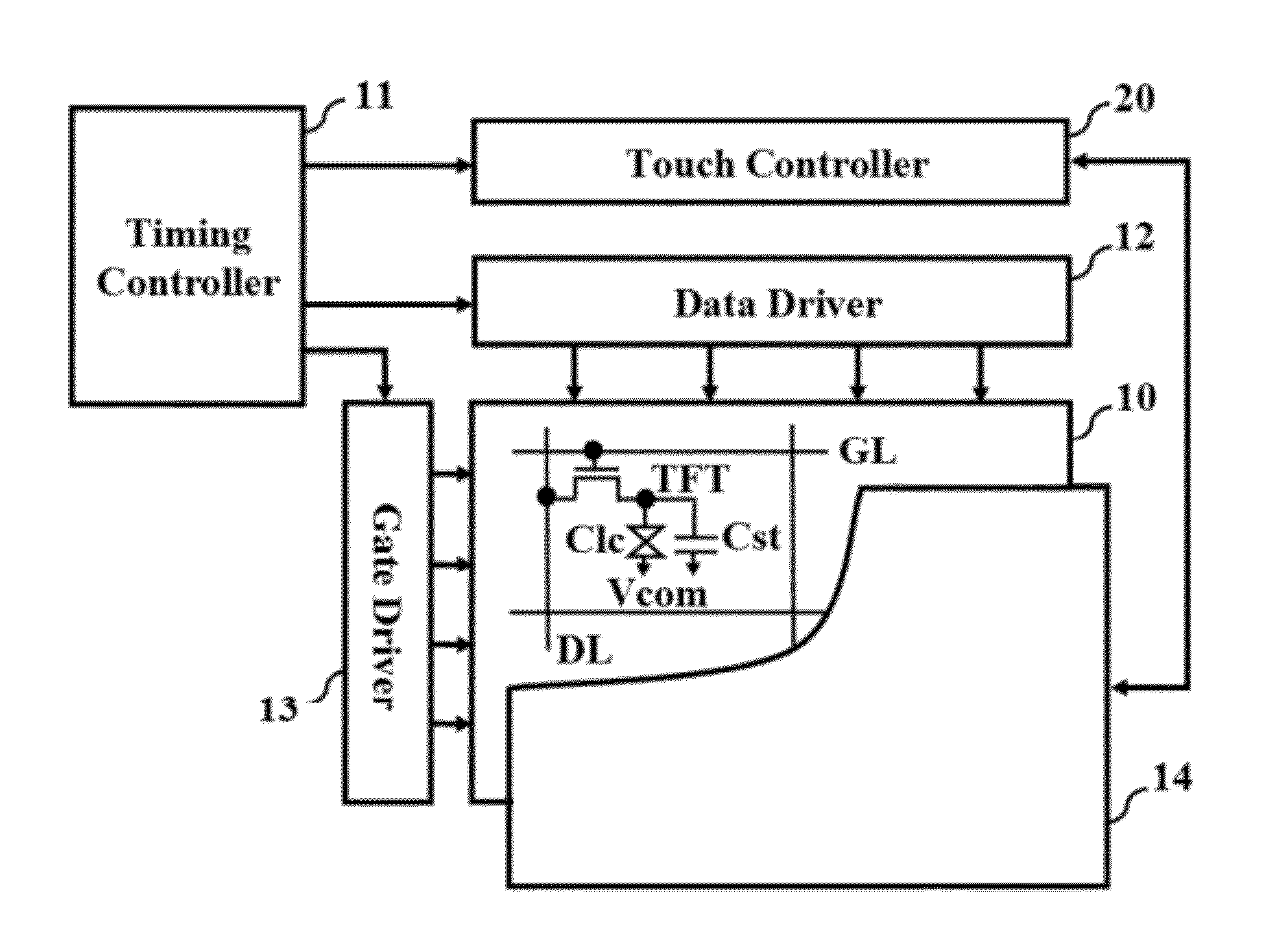
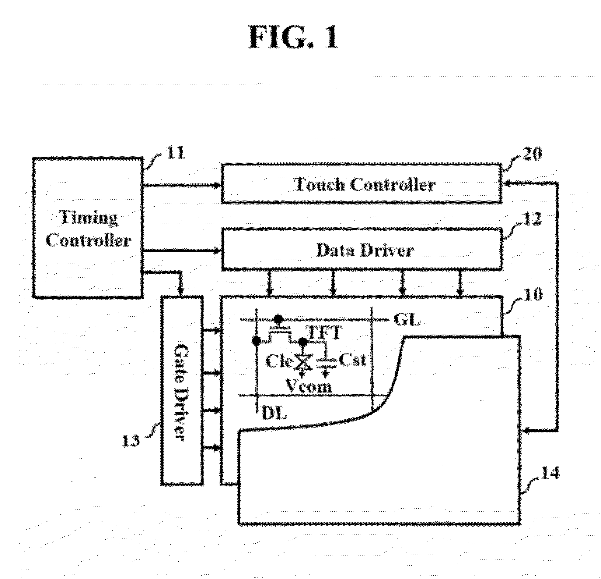
[0043]FIG. 1 illustrates a block diagram of a driving unit of a display device having a touch sensor in accordance with a preferred embodiment of the present invention, schematically.

[0044]Referring to FIG. 1, the driving unit of a display device having a touch sensor includes a touch controller 20 for driving a touch sensor 14, a data driver 12 and a gate driver 13 for driving a display panel 10, and a timing controller 11 for driving a panel driving unit including the data driver 12 and the gate driver 13. In this instance, the touch controller 20 can be integrated as one integrated circuit built in the timing controller 11.

[0045]As the display panel 10, a flat display panel, such as a liquid crystal displa...


PUM


Abstract

The present invention relates to a display device having a touch sensor in which the touch sensor is driven in a period which has a small noise component from the display device to reduce influence from the noise for minimizing a touch error; and a method for driving the same.The display device having a touch sensor includes a display panel, a panel driving unit for driving the display panel, a timing controller for controlling driving timing of the panel driving unit, a touch sensor integrated with the display panel attached thereto or built therein, and a touch controller for driving the touch sensor in a no noise period excluding a period in which the noise is generated periodically from the display panel by using at least one synchronizing signal from the timing controller, and calculating touch coordinates from a signal from the touch sensor and forwarding the touch coordinates.

Description

CROSS REFERENCE TO RELATED APPLICATION[0001]This application claims the benefit of the Patent Korean Application No. 10-2010-0087638, filed on Sep. 9, 2010, which is hereby incorporated by reference as if fully set forth herein.BACKGROUND OF THE DISCLOSURE[0002]1. Field of the Disclosure[0003]The present invention relates to display devices, and more particularly to a display device having a touch sensor in which influence of noise from a display device is reduced for minimizing a touch error; and a method for driving the same.[0004]2. Discussion of the Related Art[0005]These days, the touch sensor which can input information by touching a screen of various display devices is widely applied to a computer system as an information input device. Since the touch sensor enables a user to move or select displayed information by simple touch of the screen with a finger or a stylus s, everybody can use the touch sensor, easily.[0006]The touch sensor provides touch information by sensing a t...

Claims


Application Information

Patent Timeline
Patent Type & Authority Applications(United States)
IPC IPC(8): G06F3/041
CPCG06F3/0418G06F3/044G09G3/3648G02F1/13338G09G2310/08G09G2330/06G09G2300/0434G06F3/04184G06F3/0448G06F3/0446
Inventor KIM, SUNG-CHULKYEONG, CHANG-SUMYOUNG, DAE-JINYI, DAE-KYUKIM, SUNG-HOSHIN, SEUNG-ROK
Owner LG DISPLAY CO LTD
Learn More