
Physical separation and sequestration of carbon dioxide from the exhaust gases of fossil fuel combustion

a technology of carbon dioxide and exhaust gases, which is applied in the direction of electrostatic separation, magnesium compounds, hydrogen sulfides, etc., can solve the problems of increasing the cost of cosub>2 /sub>separation and reducing efficiency

Inactive Publication Date: 2012-03-08
ZAUDERER BERT
View PDF0 Cites 20 Cited by
  • Summary
  • Abstract
  • Description
  • Claims
  • Application Information

AI Technical Summary

Benefits of technology

[0013]The CO2 removal is implemented by operating fossil fuel fired combustors in said energy systems at a stoichiometric ratio of unity, which eliminates all excess oxygen and maximizes the carbon dioxide in the products of combustion, which facilitates the separation of carbon dioxide from the nitrogen in the combustion gas exhaust.
[0014]The removal of excess oxygen requires closing all wall openings in coal, oil, or gas fired boilers to eliminate significant air infiltration. Also, for combustion in gas turbines, blade cooling is to be implement with carbon dioxide, instead of air, which dilutes the CO2 in the gas exhaust and decreases the efficiency and increases the cost of CO2 separation.
[0022]Simultaneously the water is recovered from the lower chamber, reused by re-pressurization in order to repeat the carbon dioxide removal process with new carbon dioxide and nitrogen fossil fuel combustion products, which enables continued use of much of the water and eliminates the risk of said water becoming contaminated from leached underground hazardous materials, such as hazardous trace metals and other underground contaminants.

Problems solved by technology

Also, for combustion in gas turbines, blade cooling is to be implement with carbon dioxide, instead of air, which dilutes the CO2 in the gas exhaust and decreases the efficiency and increases the cost of CO2 separation.

Method used


Image

  • Physical separation and sequestration of carbon dioxide from the exhaust gases of fossil fuel combustion

Examples


Embodiment Construction

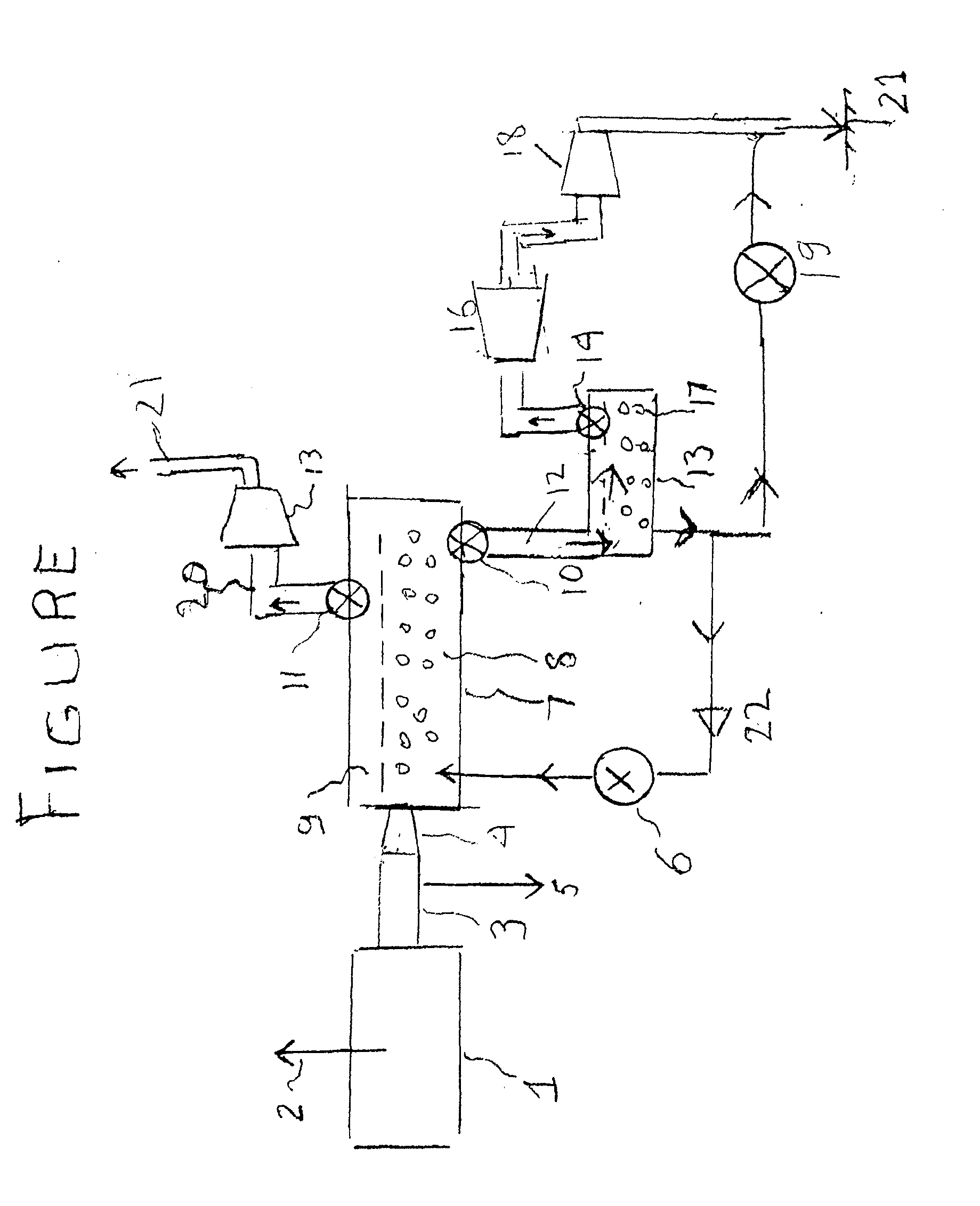
[0025]The following narrative fully describes how to practice this invention. Therefore, the details in the schematic in the FIGURE are presented as a summary at the end of this Section

[0026]The present invention discloses a totally novel method whereby carbon dioxide can be physically separated from nitrogen in a combustion gas exhaust in a manner that facilitates permanent carbon dioxide sequestration in underground limestone formations. This method is far less costly and requires much less power than chemical separation. It is also less costly and more efficient than using oxygen combustion. Furthermore, the new method discloses further improvements over the prior art in U.S. Pat. No. 7,282,189 where the present Inventor, Zauderer, disclosed methods by which CO2 can be separated from nitrogen and sequestered. That patent was for coal, while the present invention can be practiced with all fossil fuels. These prior methods as well as the present one depend on using the much lower s...


PUM

PropertyMeasurementUnit
Pressureaaaaaaaaaa
Pressureaaaaaaaaaa
Lengthaaaaaaaaaa

Abstract

Methods are provided for physically removing all the carbon dioxide from the combustion products of solid, liquid, and gaseous fossil fuels. The combustors operate without excess air to maximize the carbon dioxide at the exhaust, which is compressed with the nitrogen and mixed with pressurized water to dissolve the carbon dioxide in a chamber from which the nitrogen gas is removed. The solution is drained into a second lower pressure chamber from which the carbon dioxide re-evolves as a gas, which is then pressurized for sequestration in limestone formations as calcium bicarbonate. The water is recycled to repeat the separation process, and depressurization of the two gases recovers most of the compression energy.

Description

CROSS REFERENCE TO RELATED APPLICATIONS[0001]The present application is a non-provisional application of U.S. Application Ser. No. 61 / 380,913, filed on Sep. 8, 2010, the contents of which are incorporated by reference herein in their entirety.BACKGROUND OF THE INVENTION[0002]1. Field of the Invention[0003]The present invention relates to methods for removing and sequestering carbon dioxide (CO2) from coal fired boilers and furnaces.[0004]2. Description of Related Art[0005]Bert Zauderer in U.S. Pat. No. 7,282,189, disclosed processes and methods whereby carbon dioxide (CO2) in the exhaust from the combustion in air of carbon in coal is physically separated from nitrogen (N2). Said separation is implemented by pressurizing the CO2 and N2 gas mixture with water all at the same pressure and in sufficient water quantity to dissolve the CO2 in the water. This is followed by exhaust of the N2, which is approximately 60 times less soluble in water and remains in the gas phase. The pressuriz...

Claims


Application Information

Patent Timeline
IPC IPC(8): C01F11/18
CPCB01D53/62B01D2251/404Y02C10/04B01D2258/0283C01F11/18B01D2257/504Y02P20/151Y02C20/40
Inventor ZAUDERER, BERT
Owner ZAUDERER BERT
Learn More