Contact developing method, image forming apparatus, and process cartridge

a developing method and development method technology, applied in the field of contact developing method, image forming apparatus, and process cartridge, can solve the problems of discontinuous and drastic changes in latent image potential, inability to quickly supply toner particles to the image bearing member, and inability to achieve high-quality results

Active Publication Date: 2012-03-08
RICOH KK
View PDF5 Cites 26 Cited by
  • Summary
  • Abstract
  • Description
  • Claims
  • Application Information

AI Technical Summary

Benefits of technology

[0017]Exemplary aspects of the present invention are put forward in view of the above-described circumstances, and provide novel contact developing method, image forming apparatus, and

Problems solved by technology

This causes undesirable image density variation or white blanks in the edge portions of an image in which the latent image potential is discontinuously and drastically changed.
Therefore, when developer particles reach the trailing edge of the solid image after passing through the background portion with respect to the moving direction of the electrostatic latent image, toner particles cannot be quickly supplied to the image bearing member.
Thus, white blanks undesirably appear in the trailing edge of the solid image.
When the linear speed of the developing sleeve is greater than that of the image bearing member, various problems occur such that white blanks appear in the trailing edge of image, as described above, lateral lines get thin, vertical lines get thick, sharpness of texts decreases, and

Method used


Image

  • Contact developing method, image forming apparatus, and process cartridge
  • Contact developing method, image forming apparatus, and process cartridge
  • Contact developing method, image forming apparatus, and process cartridge

Examples


example 1

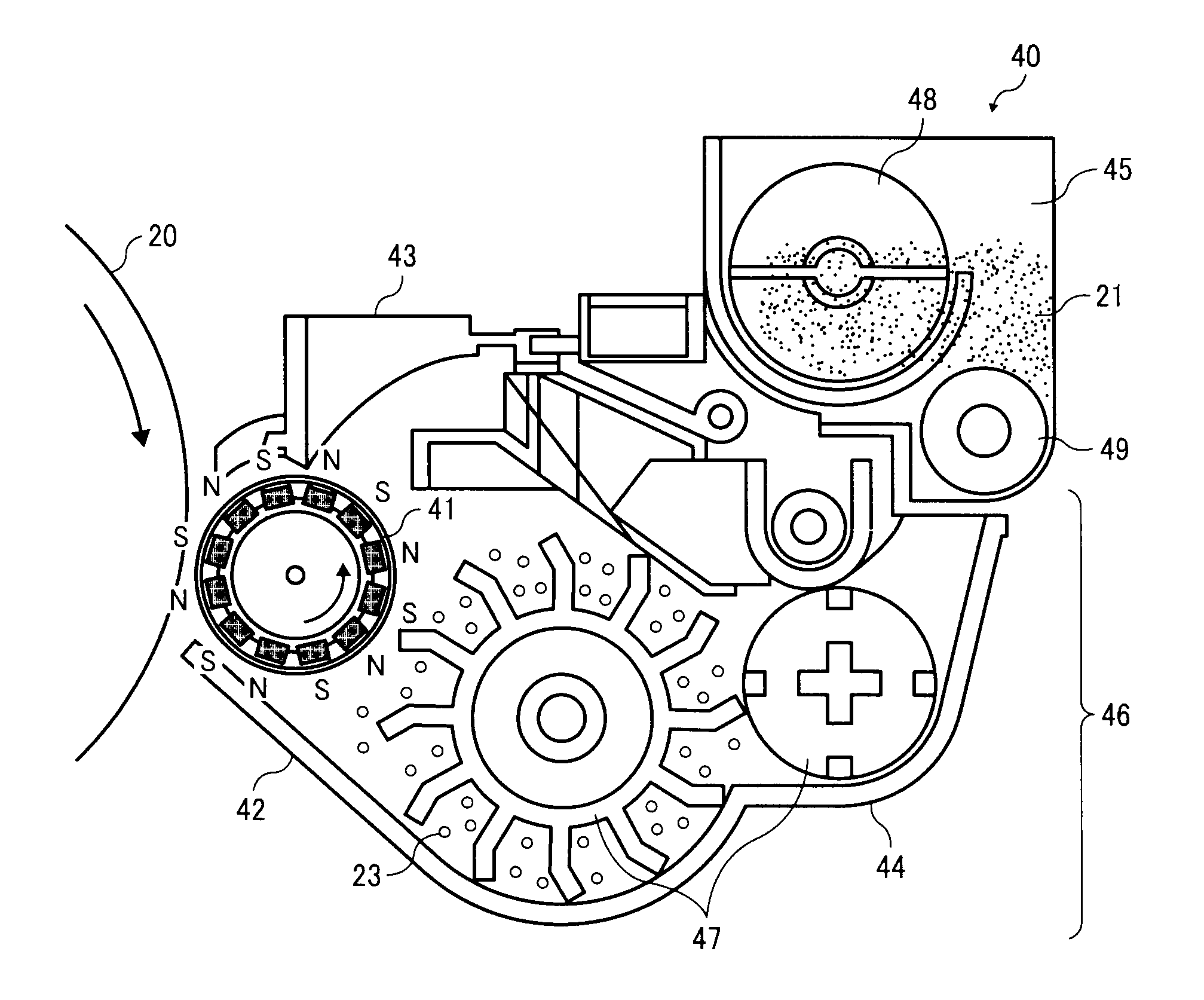
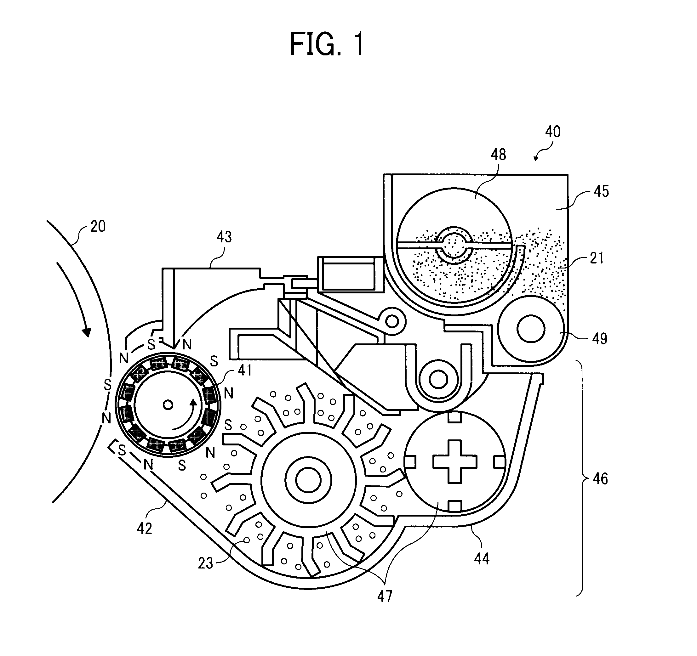
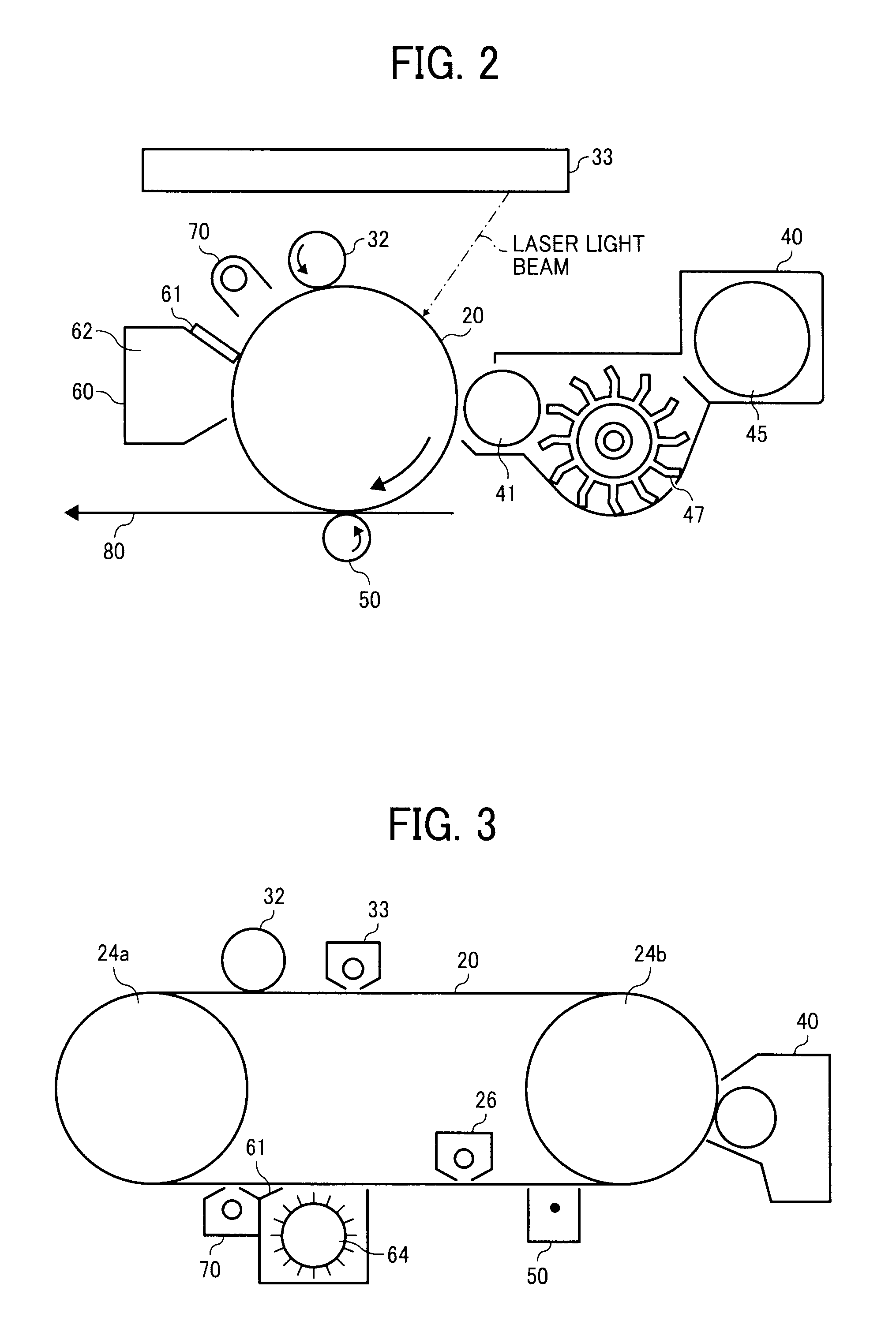
[0198]A digital image forming apparatus IMAGIO NEO C600 (from Ricoh Co., Ltd.) is modified such that the magnet fixed inside the developing sleeve is replaced with a rotatable cylindrical ferrite magnet having 12 magnetic poles, the surface of which has a magnetization of 800 Gauss, that rotates within the developing sleeve at 2,000 rpm or less. The developer A is set in this modified image forming apparatus and developing conditions are set as follows.

[0199]Developing gap (i.e., A distance between photoreceptor and developing sleeve): 0.3 mm

[0200]Doctor gap (i.e., A distance between developing sleeve and doctor blade): 0.5 mm

[0201]Linear speed of photoreceptor: 282 mm / sec

[0202](Linear speed of developing sleeve) / (Linear speed of photoreceptor): 1.1

[0203]Developing area width: 5 mm

[0204]Rotation number of magnet roller: 1,000 rpm / 0 rpm

[0205]Rotation direction of magnet roller: Opposite to rotation direction of developing sleeve

[0206]Writing density: 600 dpi

[0207]Charged potential (V...

example 2

[0224]The procedure in Example 1 is repeated except for replacing the developer A with the developer B.

example 3

[0225]The procedure in Example 1 is repeated except for replacing the developer A with the developer C.


PUM


Abstract

A contact developing method including supplying a two-component developer to an electrostatic latent image on a rotating image bearing member by rotating a developing sleeve and a rotatable magnet having multiple magnetic poles provided inside the developing sleeve, to develop the electrostatic latent image into a toner image. The developing sleeve and the image bearing member rotate in the same direction while facing each other. The two-component developer comprises a non-magnetic toner and a carrier. The carrier comprises a magnetic core particle and a resin layer covering the magnetic core particle. The resin layer comprises a conductive particle and a resin. The conductive particle comprises an alumina-based material and a conductive layer covering the alumina-based material. The resin is obtained by heating a copolymer comprising a monomer A unit and a monomer B unit.

Description

CROSS-REFERENCE TO RELATED APPLICATIONS[0001]The present patent application claims priority pursuant to 35 U.S.C. §119 from Japanese Patent Application No. 2010-200386, filed on Sep. 7, 2010, which is hereby incorporated by reference herein in its entirety.BACKGROUND[0002]1. Field of the Invention[0003]The present invention relates to a method of developing electrostatic latent image with a two-component developer comprising a non-magnetic toner and a magnetic carrier. In addition, the present invention also relates to an image forming apparatus and a process cartridge including the two-component developer.[0004]2. Description of the Background[0005]In electrophotographic image formation, an electrostatic latent image is formed on an image bearing member comprising a photoconductive material, and the electrostatic latent image is developed into a toner image with a charged toner. The toner image is then transferred onto and fixed on a recording medium. Electrophotographic developing...

Claims


Application Information

Patent Timeline
IPC IPC(8): G03G9/00G03G15/09
CPCG03G2215/0609G03G9/1139G03G9/1136G03G9/107
Inventor YAMAGUCHI, KIMITOSHIYAGUCHI, SHIGENORIIWATSUKI, HITOSHITAKII, MARIKOSAWADA, TOYOSHITANO, TOYOAKITOHMATSU, HIROSHISAKATA, KOICHIKISHIDA, HIROYUKIYAMADA, SAORI
Owner RICOH KK
Why Eureka
Try Eureka