Polishing apparatus and method

a technology of polishing apparatus and nozzle, which is applied in the direction of grinding machine components, manufacturing tools, lapping machines, etc., can solve the problems of affecting the accuracy of the temperature measurement, unable to obtain uniform distribution of the polishing rate, and unsuitable for measuring the temperature of other objects, so as to reduce the hardness of the membrane is lowered, and the pressure on the substrate is lowered

Active Publication Date: 2012-03-08
EBARA CORP
View PDF7 Cites 43 Cited by
  • Summary
  • Abstract
  • Description
  • Claims
  • Application Information

AI Technical Summary

Benefits of technology

[0060](1) By estimating the temperature of the membrane, the above effect of estimate of the temperature of the substrate can be obtained indirectly.
[0061](2) The membrane is thermally expanded by its temperature. Because the retainer ring is located at the outer circumferential side of the membrane, if the thermal expansion of the membrane becomes large, the expanded outer circumferential side of the membrane is brought into contact with the inner circumferential side of the retainer ring, and thus the outer circumferential side of the membrane is restrained. Then, wrinkles are formed in the membrane or the membrane is deformed, thus hindering pressurization to the substrate by the membrane. According to the present invention, because the temperature of the membrane can be grasped, an amount of thermal expansion of the membrane can be grasped, and the temperature of the membrane can be controlled so as not to bring the membrane into contact with the retainer ring.
[0062](3) When the temperature of the membrane increases, the hardness of the membrane is lowered (the membrane becomes soft), and thus especially the pressure applied to the substrate at an outer circumferential portion of the substrate is changed. Normally, the substrate is pressed by inflating the outer circumferential portion of the membrane. When t

Problems solved by technology

However, in the technology disclosed in Japanese laid-open patent publication No. 2002-301660, as a method of pressing the substrate, a membrane for forming a pressure chamber cannot be used, and thus uniform distribution of the polishing rate cannot be obtained.
However, in the open-type air bag, a pressurized fluid leaks during polishing, or water or a polishing liquid enters an open part of the air bag to hinder accurate measurement of the temperature.
Further, as disclosed in Japanese laid-open patent publication No. 2005-268566, in the case where the temperature of the substrate is measured by an infrared radiation thermometer which is widely used, because the infrared light passes through a silicon wafer, the infrared radiation thermometer can measure only a temperature of a wafer having a metal film and is unsuitable for measuring temperatures o

Method used


Image

  • Polishing apparatus and method
  • Polishing apparatus and method
  • Polishing apparatus and method

Examples


Embodiment Construction

[0086]A polishing apparatus according to embodiments of the present invention will be described below with reference to FIGS. 1 through 22. Like or corresponding parts are denoted by like or corresponding reference numerals throughout drawings and will not be described below repetitively.

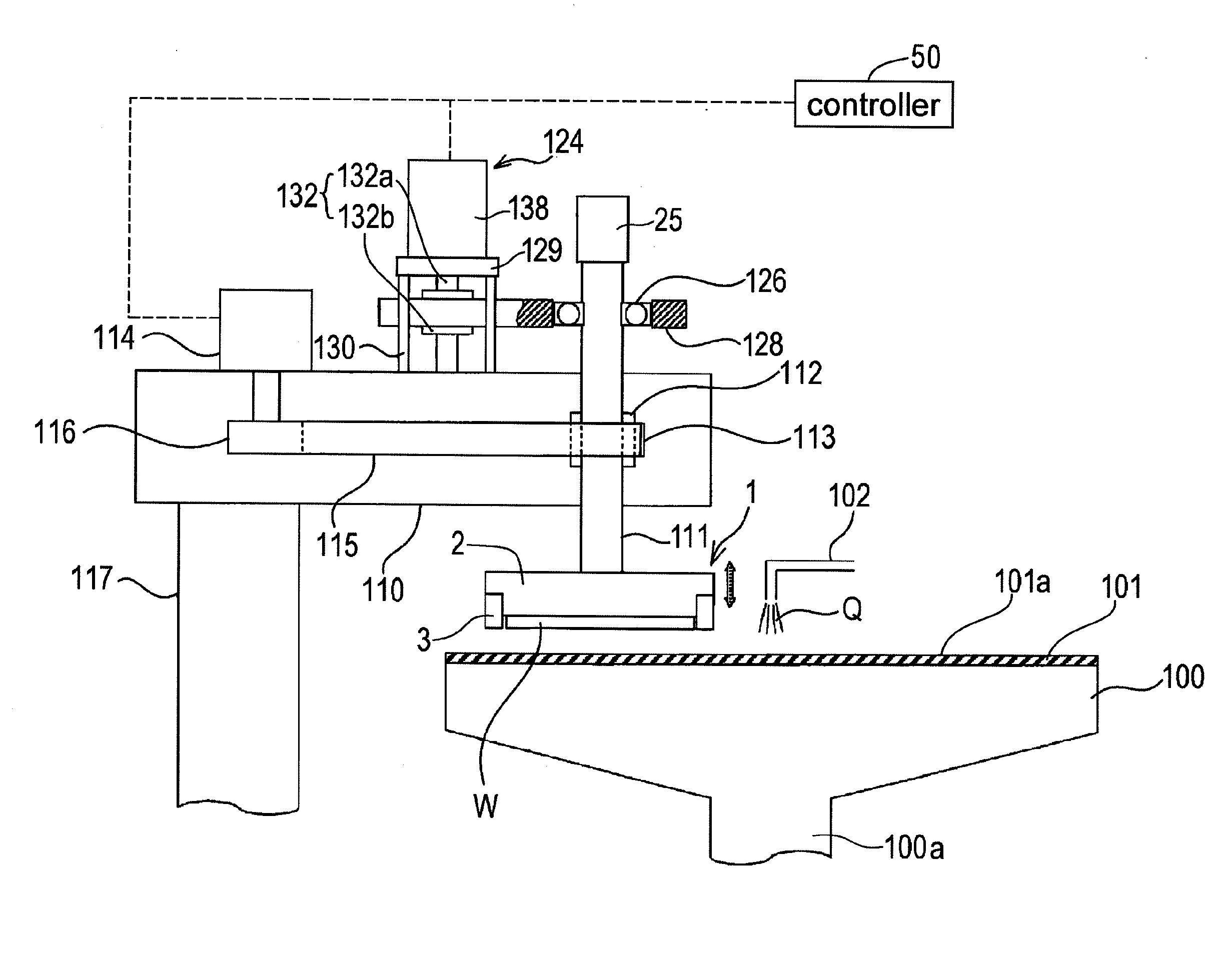
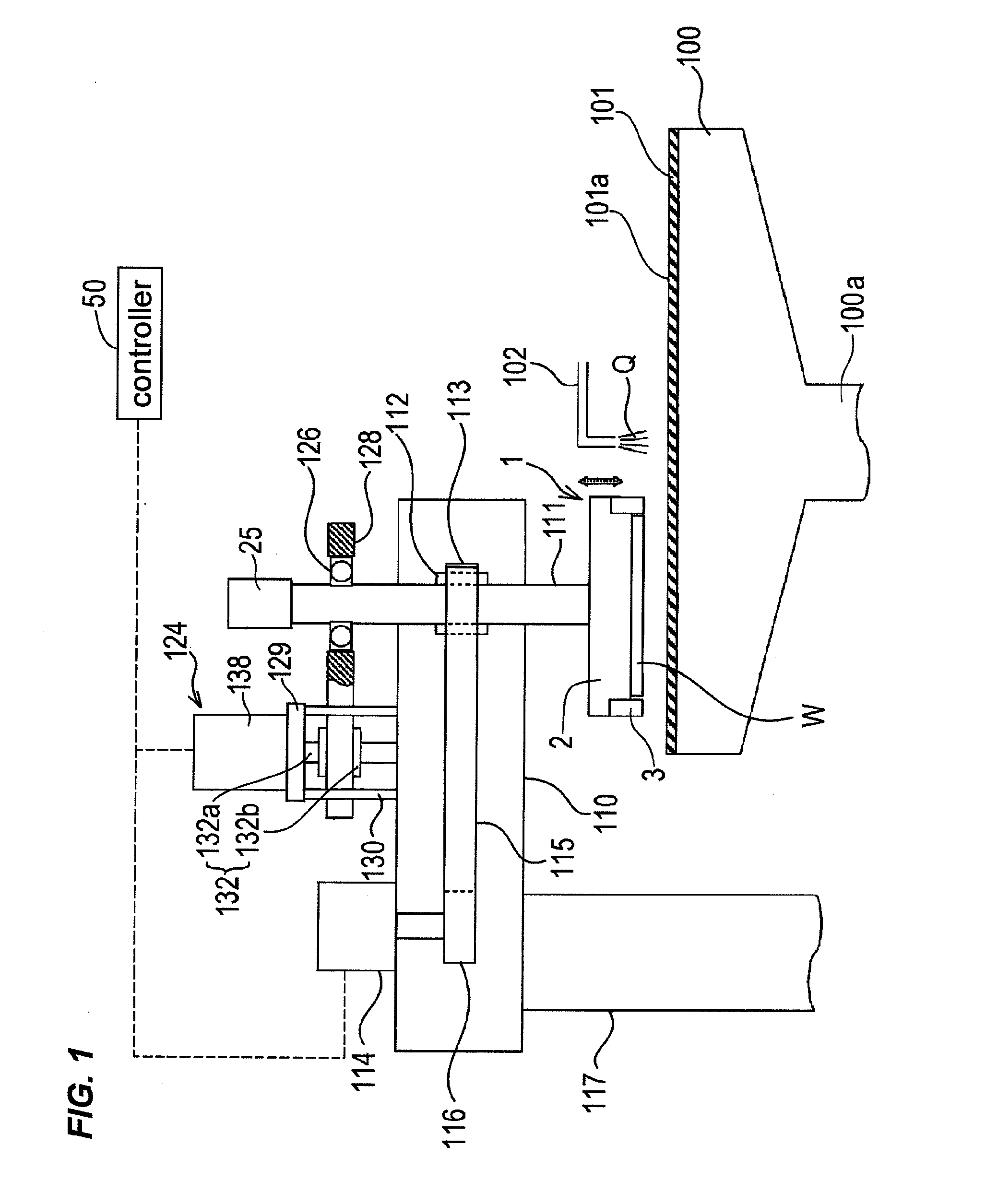
[0087]FIG. 1 is a schematic view showing an entire structure of a polishing apparatus according to an embodiment of the present invention. As shown in FIG. 1, the polishing apparatus comprises a polishing table 100, and a top ring 1 for holding a substrate such as a semiconductor wafer as an object to be polished and pressing the substrate against a polishing surface on the polishing table 100.

[0088]The polishing table 100 is coupled via a table shaft 100a to a motor (not shown) disposed below the polishing table 100. Thus, the polishing table 100 is rotatable about the table shaft 100a. A polishing pad 101 is attached to an upper surface of the polishing table 100. An upper surface 101a of the poli...


PUM


Abstract

A polishing is used for polishing a substrate such as a semiconductor wafer to a flat mirror finish. The polishing apparatus includes a polishing table having a polishing surface, a substrate holding apparatus configured to hold the substrate and to press the substrate against the polishing surface, and a controller. The substrate holding apparatus includes an elastic membrane configured to form a substrate holding surface which is brought into contact with the substrate, a carrier provided above the elastic membrane, at least one pressure chamber formed between the elastic membrane and the carrier, and an infrared light detector configured to measure thermal energy from the elastic membrane. The controller calculates an estimate value of a temperature of the elastic membrane using a measured value of the infrared light detector.

Description

BACKGROUND OF THE INVENTION[0001]1. Field of the Invention[0002]The present invention relates to a polishing apparatus and method, and more particularly to a polishing apparatus and method for polishing an object to be polished (substrate) such as a semiconductor wafer to a flat mirror finish.[0003]2. Description of the Related Art[0004]In recent years, high integration and high density in semiconductor device demands smaller and smaller wiring patterns or interconnections and also more and more interconnection layers. Multilayer interconnections in smaller circuits result in greater steps which reflect surface irregularities on lower interconnection layers. An increase in the number of interconnection layers makes film coating performance (step coverage) poor over stepped configurations of thin films. Therefore, better multilayer interconnections need to have the improved step coverage and proper surface planarization. Further, since the depth of focus of a photolithographic optica...

Claims


Application Information

Patent Timeline
IPC IPC(8): B24B49/00B24B41/06
CPCB24B37/30B24B37/015B24B37/005B24B37/10H01L21/67017H01L21/67092H01L21/6838
Inventor FUKUSHIMA, MAKOTOWATANABE, KATSUHIDEYASUDA, HOZUMIYAMAKI, SATORU
Owner EBARA CORP
Why Eureka
Try Eureka