Engine control system

a control system and engine technology, applied in the direction of machines/engines, process and machine control, electric devices, etc., can solve the problems of increasing energy loss, reducing efficiency, and energy loss, and achieve the effect of improving efficiency

Inactive Publication Date: 2012-03-08
TOYOTA JIDOSHA KK
View PDF13 Cites 10 Cited by
  • Summary
  • Abstract
  • Description
  • Claims
  • Application Information

AI Technical Summary

Benefits of technology

[0006]An object of the present invention is to provide an engine control system which is designed to improve the efficiency when a vehicle is backing up.

Problems solved by technology

At this time, in each case, energy loss occurs.
In this case, the greater the amount of electric power which is generated by one motor generator and which is consumed by the other motor generator, the greater the energy loss and therefore the lower the efficiency.
That is, the larger the output torque of the engine, the greater the amount of electric power which is generated by the second motor generator and which is consumed by the first motor generator and therefore the greater the energy loss.
In this case, in this vehicle, since the output of the engine is always made maximum, the amount of electric power which is generated by the second motor generator and which is consumed by the first motor generator becomes extremely large and therefore there is the problem of the efficiency ending up dropping.

Method used


Image

  • Engine control system
  • Engine control system
  • Engine control system

Examples


Embodiment Construction

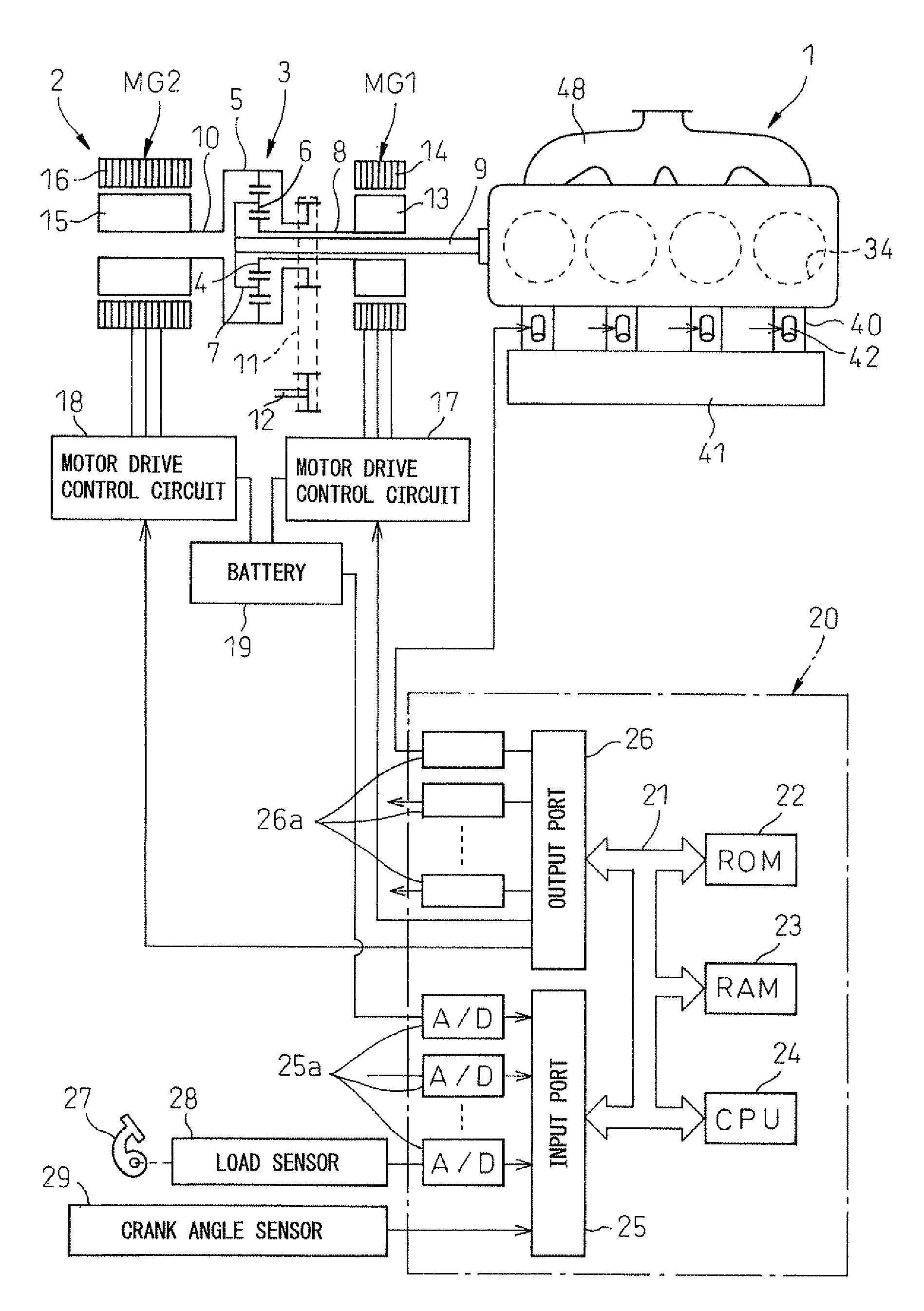
[0028]FIG. 1 is an overview of a spark ignition type engine 1 and an output regulating system 2 mounted in a hybrid type vehicle.

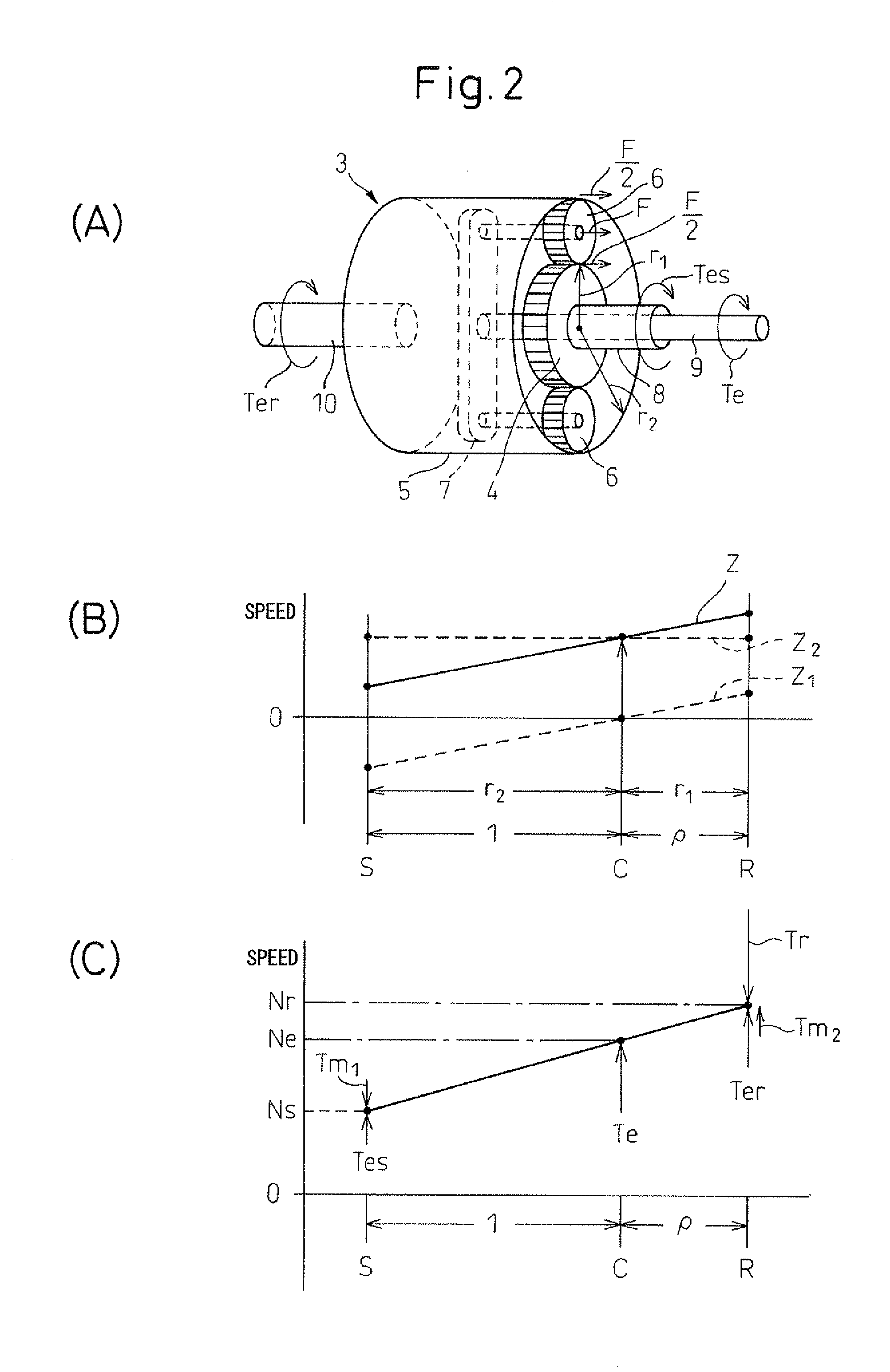
[0029]First, referring to FIG. 1, the output regulating system 2 will be simply explained. In the embodiment shown in FIG. 1, the output regulating system 2 is comprised of a pair of motor generators MG1 and MG2 operating as electric motors and generators and a planetary gear mechanism 3. This planetary gear mechanism 3 is provided with a sun gear 4, a ring gear 5, planet gears 6 arranged between the sun gear 4 and the ring gear 5, and a planetary gear carrier 7 carrying the planet gears 6. The sun gear 4 is coupled to a shaft 8 of the motor generator MG1, while the planetary gear carrier 7 is coupled to an output shaft 9 of the engine 1. Further, the ring gear 5 on the one hand is coupled to a shaft 10 of the motor generator MG2 and on the other hand is coupled to an output shaft 12 coupled to the drive wheels through a belt 11. Therefore, it is learned t...


PUM


Abstract

A hybrid type vehicle designed to use an engine and motor generators to drive the vehicle, wherein the engine is provided with a variable compression ratio mechanism and a variable valve timing mechanism. When the vehicle is backing up, one motor generator is used to generate an output for vehicle drive use. If the engine is made to operate at this time, the engine torque and the engine speed are made to change along a minimum fuel consumption rate operation line.

Description

TECHNICAL FIELD[0001]The present invention relates to an engine control system.BACKGROUND ART[0002]Known in the art is a hybrid type vehicle which is provided with an output regulating system which has a pair of motor generators and which receives as input the output of an engine and generates output for driving the vehicle, wherein the output regulating system has a planetary gear mechanism comprised of a sun gear, a ring gear, and planet gears carried on a planetary carrier, a first motor generator is coupled to the ring gear, the engine and second motor generator are coupled to the sun gear, and the planetary carrier is coupled to an output shaft for driving the vehicle (see Japanese Patent No. 3337026).[0003]When providing a pair of motor generators in this way, often the electric power which is generated by one motor generator is used to drive the other motor generator or the electric power which is generated by the other motor generator is stored in a battery and the electric ...

Claims


Application Information

Patent Timeline
Patent Type & Authority Applications(United States)
IPC IPC(8): B60W20/00B60W10/06B60L50/16
CPCB60K1/02B60K6/365B60K6/445B60L2220/14B60L2240/421B60L2240/423B60L2240/441B60L2240/443B60W10/06B60W10/08B60W20/00B60W30/18036B60W30/1882B60W2540/10B60L50/16B60L50/61F02D13/0234F02D15/04F02D29/06F02D31/006F02D41/021F02D2041/001F02D2250/26F02D2700/03Y02T10/12Y02T10/62Y02T10/64Y02T10/70Y02T10/7072
Inventor NAKAZONO, HIDEKIAKIHISA, DAISUKE
Owner TOYOTA JIDOSHA KK
Why Eureka
Try Eureka