Vacuum pump with ventilating means

a vacuum pump and ventilating technology, applied in the field of vacuum pumps, can solve problems such as negative consequences, and achieve the effect of more operational stability of vacuum pumps

Inactive Publication Date: 2012-03-15
SCHWABISCHE HUTTENWERKE AUTOMOTIVE CMBH
View PDF0 Cites 30 Cited by
  • Summary
  • Abstract
  • Description
  • Claims
  • Application Information

AI Technical Summary

Benefits of technology

[0004]The invention aims to make vacuum pumps more operationally stable

Problems solved by technology

This counteracts the suctioning of fluid and thus filling of the delivery chamber with

Method used


Image

  • Vacuum pump with ventilating means
  • Vacuum pump with ventilating means
  • Vacuum pump with ventilating means

Examples


Embodiment Construction

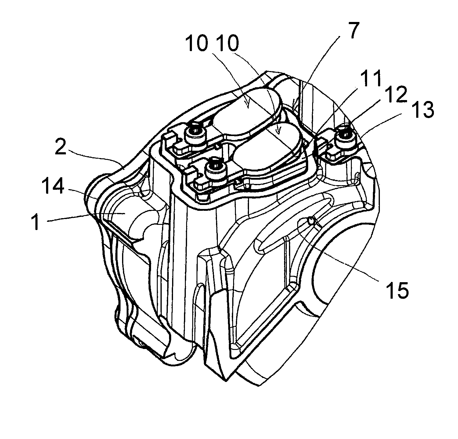
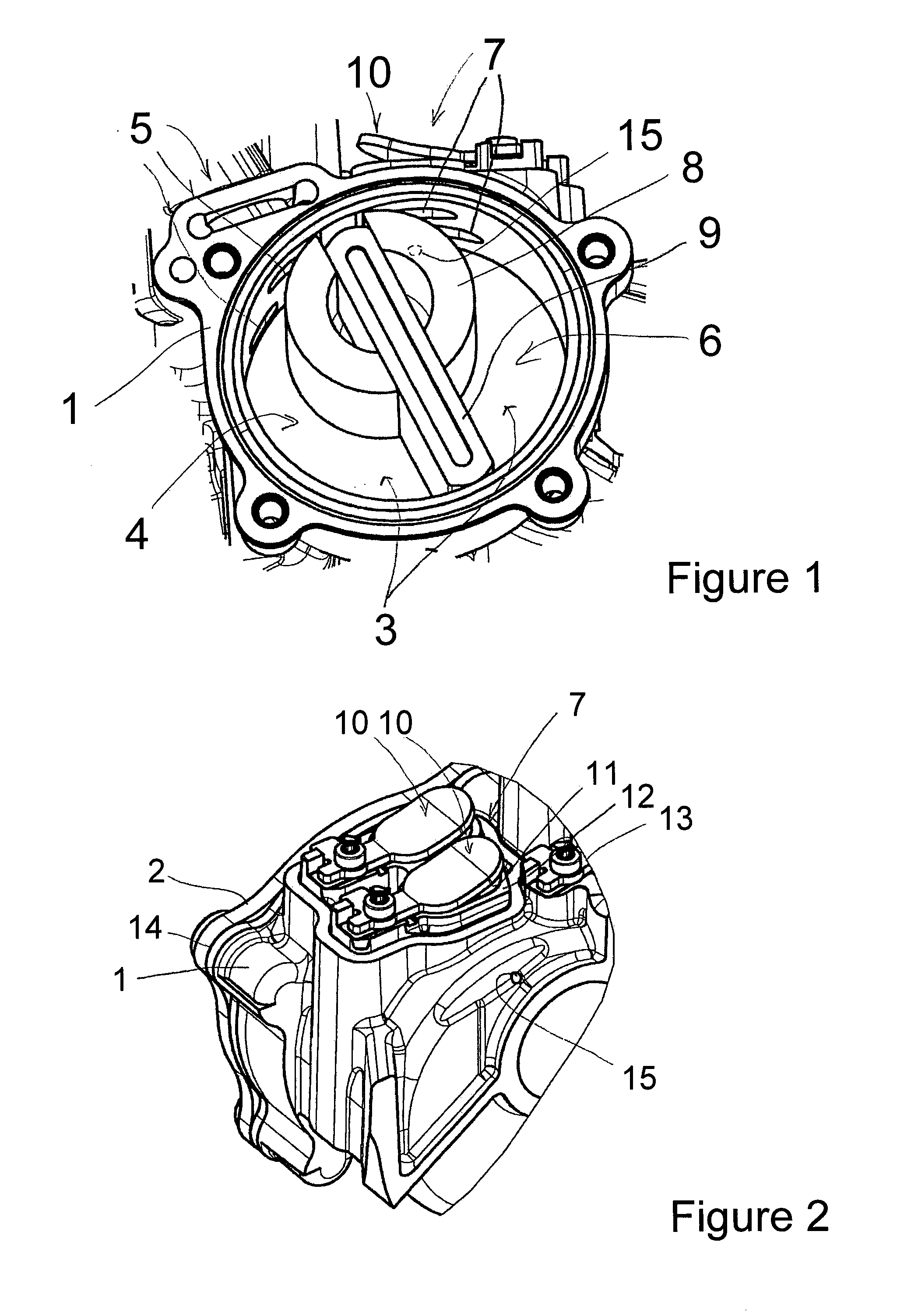
[0028]FIG. 1 shows a vacuum pump of a first exemplary embodiment, in a perspective view onto a housing 1 of the vacuum pump. A housing cover is removed, such that a delivery chamber 3 which is surrounded by the housing 1 and the housing cover when they are assembled is exposed. A delivery member comprising a rotor 8 and a vane 9 is movably arranged in the delivery chamber 3. The vacuum pump is for example embodied as a vane cell pump, wherein a single-vane vacuum pump serves as an example. When the delivery member 8, 9 is rotary-driven anti-clockwise, a low-pressure region 4 comprising a working inlet 5 and a high-pressure region 6 comprising a working outlet 7 are formed in the delivery chamber 3. The vacuum pump is connected to an assembly, for example a brake booster of a motor vehicle, via the working inlet 5 in order to supply the assembly with a negative pressure. When the delivery member 8, 9 is rotary-driven, air is suctioned into the low-pressure region 4 through the workin...


PUM


Abstract

A vacuum pump for supplying a machine assembly with a negative pressure includes a housing and a housing cover surrounding a delivery chamber. The delivery chamber includes a low-pressure region having a working inlet connected to the assembly, and a high-pressure region having a working outlet. A delivery member moveable within the delivery chamber, which, when moved, suctions air into the delivery chamber through the working inlet and expel it at an increased pressure through the working outlet. An outlet valve is arranged at or downstream or the working outlet and at least makes it difficult for air to flow back into the delivery chamber. The delivery chamber is connected to the external environment of the vacuum pump via a ventilating connection in order to establish at least partial pressure equalization with the external environment when the delivery member is stopped and a negative pressure prevails in the delivery chamber.

Description

RELATED APPLICATION DATA[0001]This application claims the priority of German patent application No. 10 2010 044 898.2-15, filed on Sep. 9, 2010, which is hereby incorporated in its entirety by reference.FIELD OF THE INVENTION[0002]The invention relates to a vacuum pump for supplying a machine assembly with a negative pressure. The assembly is assigned to a machine, preferably an engine and particularly preferably an internal combustion engine. It can be arranged directly on the machine or even within the machine or also retracted from it and can be operated together with the machine, preferably in accordance with the machine. The vacuum pump, when installed, is preferably driven by the machine, for example by a crankshaft or valve control shaft of an internal combustion engine. The invention relates in particular to a vacuum pump which is installed in a motor vehicle or is designed to be installed in a motor vehicle.BACKGROUND OF THE INVENTION[0003]Vacuum pumps in motor vehicles, fo...

Claims


Application Information

Patent Timeline
IPC IPC(8): F04B53/06F04B53/18
CPCF04C18/3442F04C29/128F04C28/06F04C25/02
Inventor PETERS, SVENMAUCHER, FRANZ
Owner SCHWABISCHE HUTTENWERKE AUTOMOTIVE CMBH
Why Eureka
Try Eureka