Optical touch control apparatus and touch sensing method thereof
- Summary
- Abstract
- Description
- Claims
- Application Information
AI Technical Summary
Benefits of technology
Problems solved by technology
Method used
Image

Examples
first embodiment
A First Embodiment
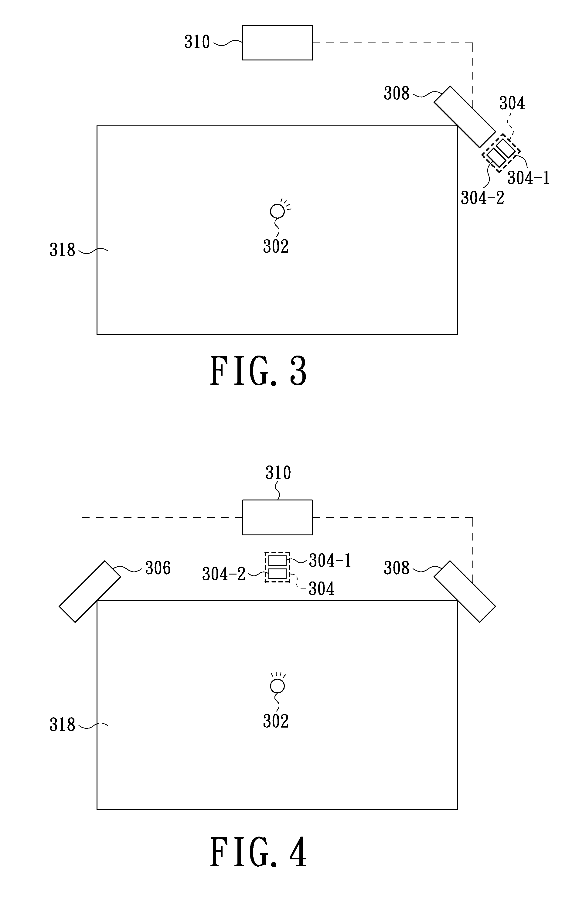
[0017]FIG. 3 is a top view of the optical touch control apparatus in accordance with a preferred embodiment of the present invention. Referring to FIG. 3, the optical touch control apparatus includes a light source supply module 304, an image sensing apparatus 308 and a processing circuit 310. The light source supply module 304 is used for supplying a first light source to illuminate an object 302 located on a plane 318. In the embodiment, the plane 318 is shaped as a parallelogram that is perfectly shaped in rectangle. The size of the plane 318 can be determined in an internal software of the processing circuit 310, or a range of the size of the plane 318 is defined by objects disposed at the four corners of the plane 318. In the embodiment, the light source supply module 304 includes a laser light source 304-1 and an optical element 304-2. The laser light source 304-1 is used for providing a first line light source. The optical element 304-2 is used for convertin...
second embodiment
A Second Embodiment
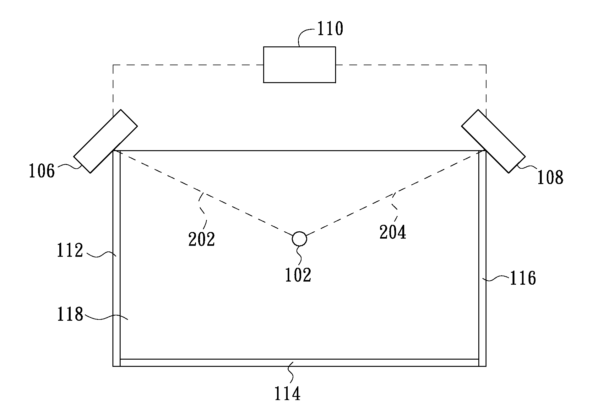
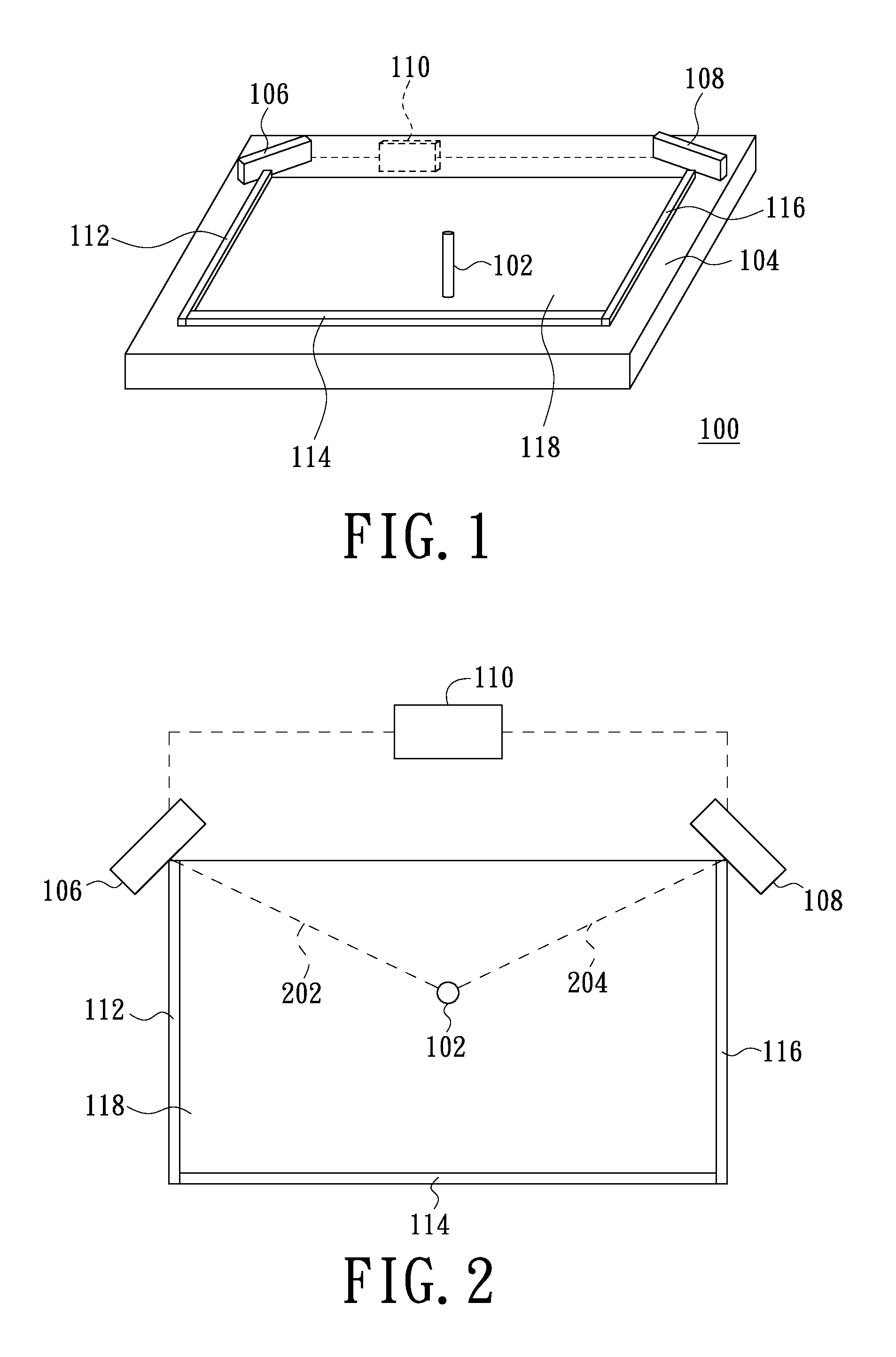
[0020]FIG. 4 is a top view of the optical touch control apparatus in accordance with another preferred embodiment of the present invention. Referring to FIG. 4, compared with the optical touch control apparatus in the first embodiment, the optical touch control apparatus in the second embodiment further includes an image sensing apparatus 306. The image sensing apparatus 306 is disposed at another corner of the plane 318, and is used for detecting the light of the first light source generated by the light source supply module 304 and reflected by the surface of the object 302 to acquire another image. In addition, the processing circuit 310 receives the image sensed by the image sensing apparatus 308, and further receives the image sensed by the image sensing apparatus 306, and calculates the position of the object 302 related to the plane 318 according to the image features of the light of the first light source reflected by the surface of the object in the acqui...
third embodiment
A Third Embodiment
[0021]FIG. 5 is a top view of the optical touch control apparatus in accordance with a third preferred embodiment of the present invention. Referring to FIG. 5, compared with the optical touch control apparatus in the second embodiment, the optical touch control apparatus in the third embodiment includes two light source supply modules respectively labeled with 304 and 312. The light source supply module 304 and 312 are respectively used for supplying a first light source and a second light source, and the light of the first light source and the second light source goes forwards the plane 318. Besides this, each of the image sensing apparatuses is used cooperating with a light source supply module.
[0022]Similar to the light source supply module 304, the light source supply module 312 includes a laser light source 312-1 and an optical element 312-2. The laser light source 312-1 is used for providing a second line light source, and the optical element 312-2 is used f...
PUM
 Abstract
Description
Claims
Application Information
 - R&D Engineer
- R&D Manager
- IP Professional
- Industry Leading Data Capabilities
- Powerful AI technology
- Patent DNA Extraction
Browse by: Latest US Patents, China's latest patents, Technical Efficacy Thesaurus, Application Domain, Technology Topic.
© 2024 PatSnap. All rights reserved.Legal|Privacy policy|Modern Slavery Act Transparency Statement|Sitemap