Smart target surveillance system

a surveillance system and target technology, applied in the field of smart target surveillance systems, can solve the problems of physical size, power consumption and reliability, and nothing disclosed in the prior art teaches the control of remote surveillance systems by software, and achieve the effect of better visualization

a surveillance system and target technology, applied in the field of smart target surveillance systems, can solve the problems of physical size, power consumption and reliability, and nothing disclosed in the prior art teaches the control of remote surveillance systems by software, and achieve the effect of better visualization

US20120062733A1Inactive Publication Date: 2012-03-15INNOVATIVE WIRELESS TECH

Image

  • Smart target surveillance system
  • Smart target surveillance system
  • Smart target surveillance system

Examples


Embodiment Construction

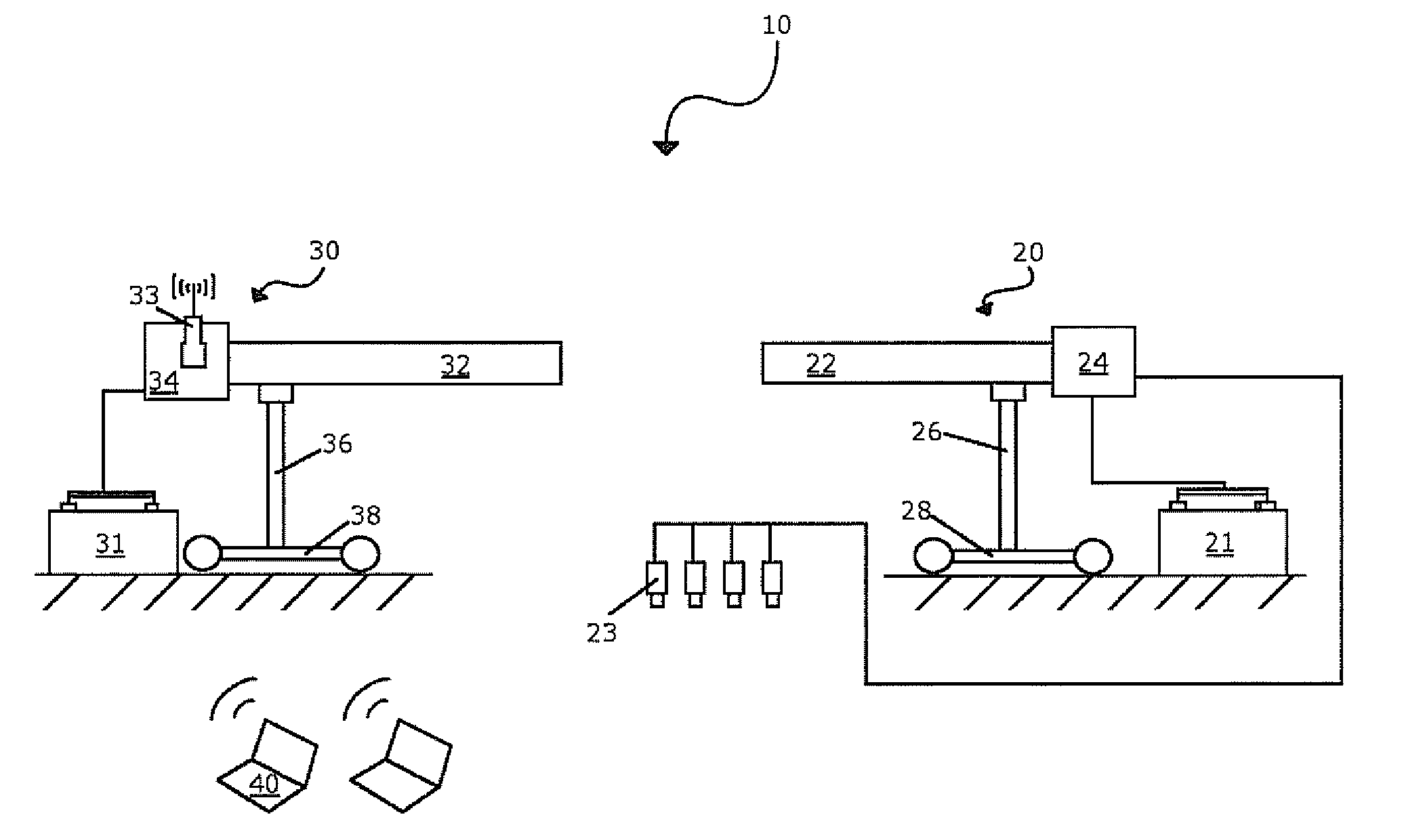
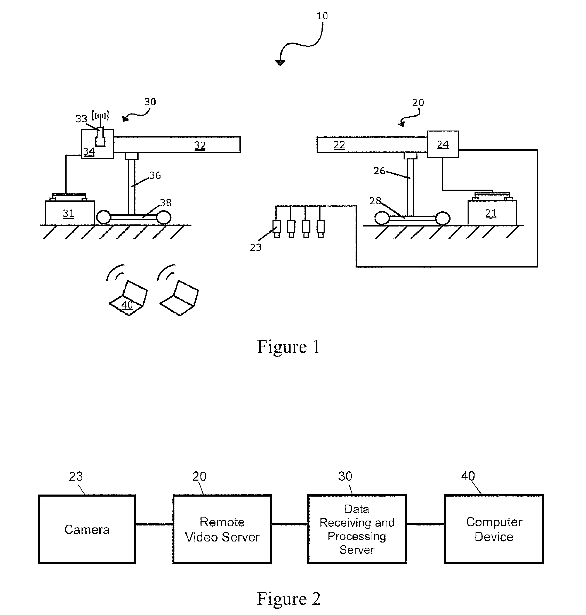
[0022]As depicted in FIG. 1, the basic components of a portable surveillance system 10 are illustrated schematically. Initially, the remote video server (RVS) unit 20 collects video data from its connected array of cameras 23 and transmits to the data receiving and processing server (DRPS) unit 30. Once the video data is received and processed, it may be accessed using software operated on a computer processor 40 (i.e., laptop or desktop computer). The RVS unit 20 and DRPS unit 30 are capable of extreme mobility and may be positioned according to specific surveillance requirements. The RVS unit 20 and DRPS unit 30 are capable of receiving and transmitting data for ultimate processing by a user.

[0023]The RVS unit 20 may be connected to the camera 23. Optionally, there may be a plurality of cameras 23 connected to a single RVS unit 20 for ultimately processing data to a single DRPS unit 30. Alternatively, specific cameras 23 may be used for specific surveillance circumstances. For ins...


PUM


Abstract

A surveillance system comprising a remote video server, a camera, a data receiving and processing server and a computer device is disclosed herein. The camera captures video and sends the video to the remote video server. The remote video server wirelessly transmits the video to the data receiving and processing server for video processing. The computer device may then securely and wirelessly connect to the data receiving and processing server to view the video.

Description

PRIORITY CLAIM[0001]This utility patent application contains subject matter claiming benefit of the priority date of U.S. Provisional Patent Application Ser. No. 61 / 296,262, filed on Jan. 19, 2010, entitled “Smart Target Surveillance System.” Accordingly, the entire contents of this provisional patent application are hereby expressly incorporated by reference.FIELD OF THE INVENTION[0002]The present invention relates generally to devices capable of remote video and audio surveillance. More particularly, the present invention relates to system and methods providing portable monitoring, recording and transmitting digital information wirelessly across long distances.BACKGROUND OF THE INVENTION[0003]Surveillance and monitoring systems have played a valuable role in many contexts. For example, surveillance video cameras are well renowned for capturing images of criminal activity within various financial and commercial institutions. Video cameras have also played an increasingly valuable r...

Claims


Application Information

Patent Timeline
15 Mar 2012
Publication
US20120062733A1
IPC
H04N7/18
CPC
H04N7/18; G08C17/00
Inventors
MIRONICHEV, SERGEI Y.; MECHLING, CHRISTOPHER D.