Light reflection sheet, light source device, and display device

Inactive Publication Date: 2012-03-15
SHARP KK
View PDF4 Cites 48 Cited by
  • Summary
  • Abstract
  • Description
  • Claims
  • Application Information

AI Technical Summary

Benefits of technology

[0050]In the present invention, the second position setting portion can be formed integrally with the support body. Therefore, it is possible to preve

Problems solved by technology

Referring to a display device including a display surface having a comparatively large area, however, it is hard to uniformly enhance the luminance characteristic over the whole surface.
However, the backlight device of the CCFL type requires high voltage components such as, for example, the inverter circuit board for discharging the cold cathode fluorescent lamp, the electrodes on the both ends of the cold cathode fluorescent lamp and the like, and it is necessary to maintain a comparatively long insulating distance around the high voltage components.
Therefore, the high voltage components hin

Method used


Image

  • Light reflection sheet, light source device, and display device
  • Light reflection sheet, light source device, and display device
  • Light reflection sheet, light source device, and display device

Examples


embodiment 1-1

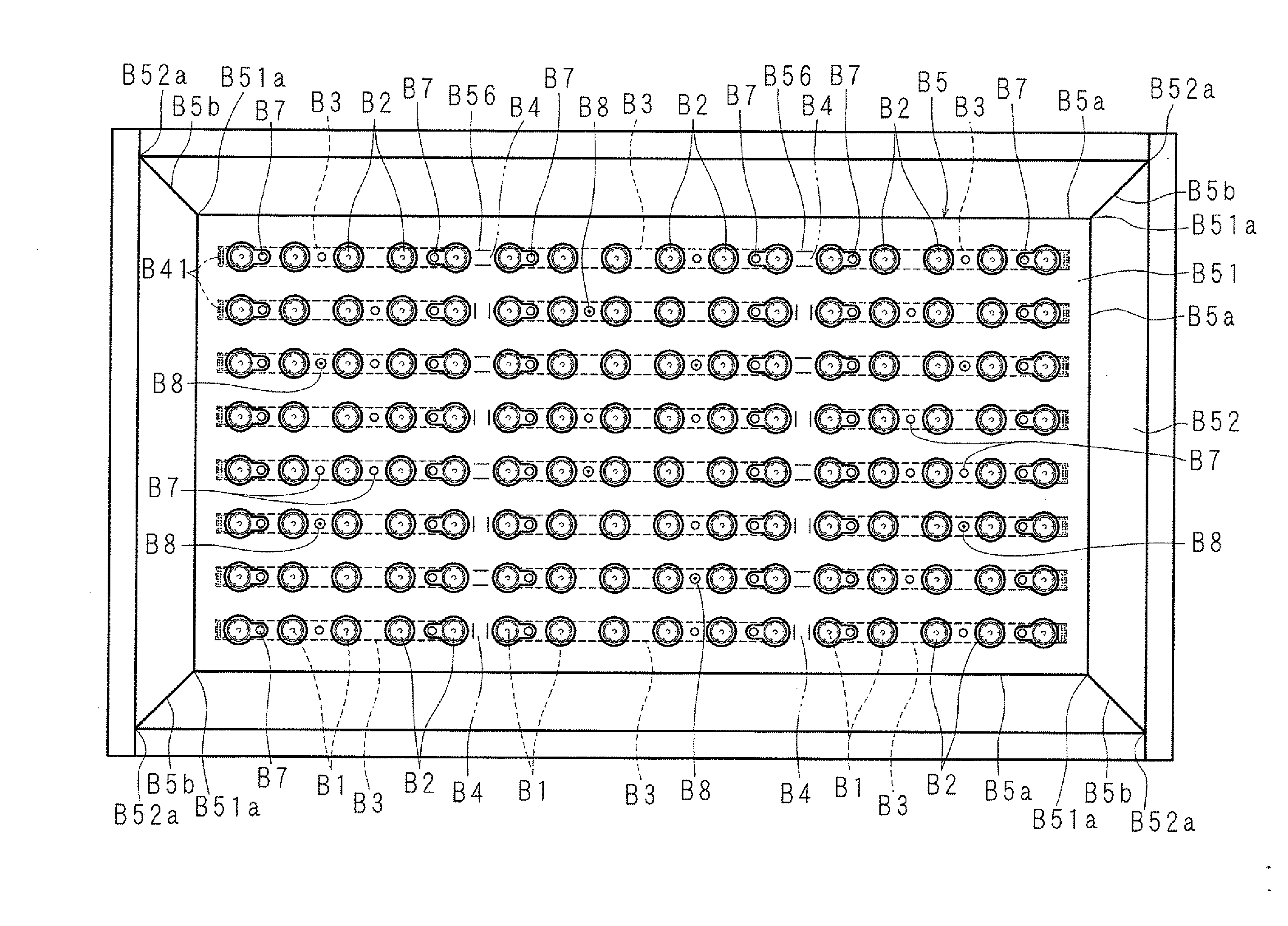
[0274]FIG. 29 is a perspective view showing a configuration of a light source device according to the present invention, FIG. 30 is a plan view showing the configuration of the light source device, FIG. 31 is a plan view showing a configuration in which a reflection sheet of the light source device is omitted, and FIG. 32 is a partially enlarged cross-sectional view showing the configuration of the light source device.

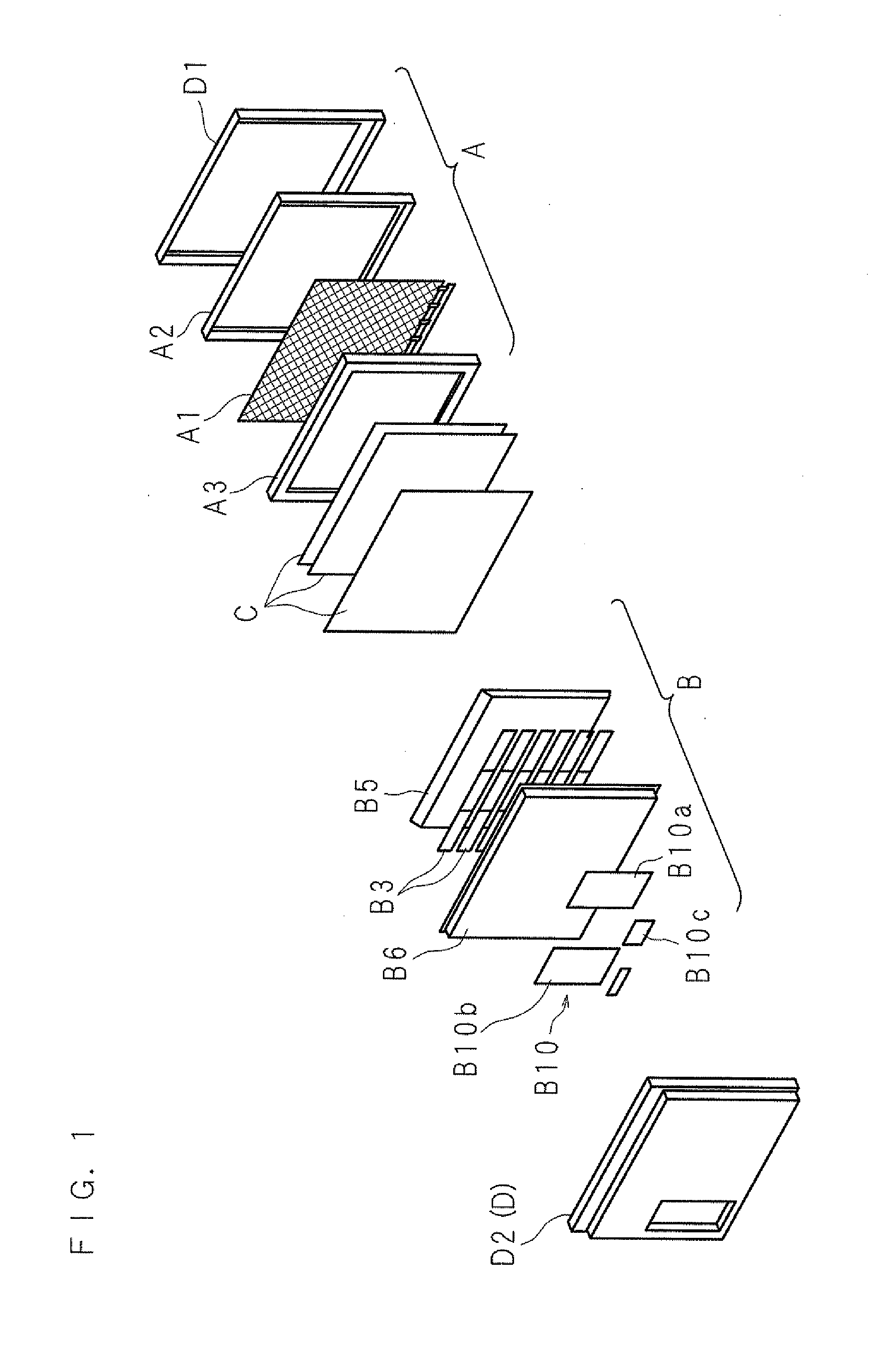
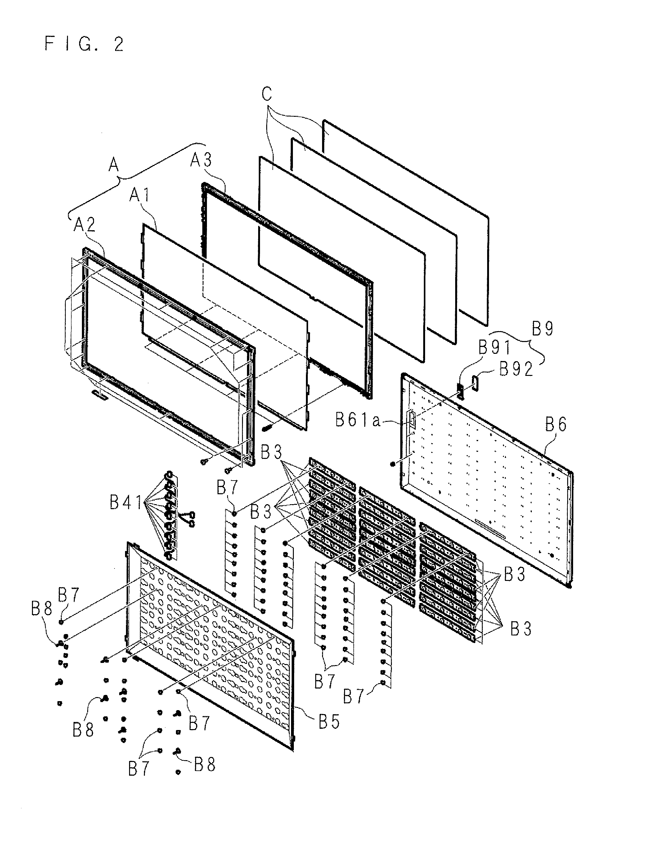
[0275]The shown light source device (B) includes a plurality of light-emitting diodes 1 (B1) that are mounted on the rear side of a roughly rectangular solid-shaped display unit (A) of a thin-type display device including a display surface on its front side and this display unit and that serve as light sources arranged on a grid, a plurality of light-emitting diode substrates 2 (B3) mounted with those light-emitting diodes 1 on one surface 2a and arranged in a plurality of lines, a plurality of connectors 3 (B4) interconnecting the neighboring light-emitting diode subs...

embodiment 1-2

[0295]FIG. 38 is an exploded front view showing another configuration of main components of a reflection sheet included in a light source device according to the present invention. Instead of forming the three second folds 53 at a corner of a frame portion 52 in a reflection sheet 5 (B5), this light source device has a roughly V-shaped defect portion 57 at a corner 52a of the frame portion 52 so that when the four frame portions 52 continuing to the four sides of a flat portion 51 at a first fold 5b are obliquely folded with respect to a flat portion 51, two edges 57a, 57a of the defect portion 57 may agree and this agreement condition may be held by double-faced tape 55.

[0296]The reflection sheet 5 made of one rectangular synthetic resin-made sheet material has the flat portion 51 smaller than the plate portion 61 of the support case 6 and the four frame portions 52 continuing to the four sides of this flat portion 51 at the first folds 5b, so that by folding each of the frame port...

embodiment 1-3

[0298]FIG. 39 is an exploded front view showing another configuration of the main components of the reflection sheet included in the light source device according to the present invention and FIG. 40 is an enlarged front view showing a further configuration of the main components of the reflection sheet. Instead of having the defect portion 57 at the corner 52a of the frame portions 52 on the flat portion 5, this light source device has three second folds 53 along the rim of the frame portion from a corner 51a of a flat portion 51 and one slit 58 in a configuration that the corner 52a of the frame portion 52 is formed at the second folds 53 and the ends of the frame portions 52 that neighbor each other at the slit 58 agree to hold the agreement condition and the corner 52a by using double-faced tape.

[0299]The slit 58 is formed along the facing two sides of the flat portion 51 from its corners 51a respectively, so that both ends of the two frame portions continuing to the facing two ...


PUM


Abstract

A through hole penetrating in a vertical direction and a slot which is separated from the through hole in the direction along the sheet surface and is long in a separating direction are provided on a light reflection sheet supported on a support body supporting a light source for reflecting light emitted from the light source, and there are provided a first shaft member fitted in the through hole for setting a position of the light reflection sheet with respect to the support body, and a second shaft member fitted in the slot to enable a relative movement in a longitudinal direction of the slot for setting the position of the light reflection sheet with respect to the support body.

Description

[0001]This application is the national phase under 35 U.S.C. §371 of PCT International Application No. PCT / JP2010 / 056809 which has an International filing date of Apr. 16, 2010 and designated the United States of America.BACKGROUND[0002]1. Technical Field[0003]The present invention relates to a display device such as a liquid crystal television, a light source device to be used as a light source of the display device, and a light reflection sheet for reflecting light applied from the light source of the light source device.[0004]2. Description of Related Art[0005]A liquid crystal display device referred to as a thin type such as a liquid crystal television includes a display unit which has, on a right side, a display surface for displaying an image and takes a shape of an almost rectangular parallelepiped, and a light source device disposed on a back side of the display unit for applying light on the display unit, and a diffusion plate and an optical sheet such as a prism sheet are ...

Claims


Application Information

Patent Timeline
IPC IPC(8): F21V7/00
CPCG02B5/08G02F1/133603G02F1/133605H05K2201/10189G02F2201/465H05K1/142H05K2201/10106G02F1/133608
Inventor TAKEUCHI, HIDETOFUJITA, TOSHIYUKISUGAHARA, TATSUOKAWAMURA, YUUKIYAHATA, MAMORUTAKAHASHI, HIROSHIITO, KEITATOSHIYUKI, KENZOITO, KENICHIRONAKAMICHI, KAZUKISASAKI, TOMOOMORIBE, KENTA
Owner SHARP KK
Why Eureka
Try Eureka