Light source device and display device provided with same

a technology of light source device and display device, which is applied in the direction of identification means, lighting and heating apparatus, instruments, etc., can solve the problems of increasing the number of process steps, reducing the number of components, and reducing the price of the display device, so as to achieve the effect of facilitating warping

Active Publication Date: 2012-03-15
SHARP KK
View PDF0 Cites 14 Cited by
  • Summary
  • Abstract
  • Description
  • Claims
  • Application Information

AI Technical Summary

Benefits of technology

[0016]In this invention, when the reflecting sheet is opposite to one surface of the circuit board having a LED mounted on the surface and the lens is disposed in the through hole of the reflecting sheet, the convex portion disposed at the edge of the through hole in the reflecting sheet is fit in between the attachment side of the lens for attachment to the surface and the surface. Thus, the reflecting sheet is easily assembled in such a manner that the reflecting sheet does not rise.
[0017]Further, in the light source device according to the present invention, such a configuration is preferable that the reflecting sheet has flexibility and, at an edge of the through hole, a slit is provided in a part opposite to the convex portion.
[0018]In this invention, the slit allows the circumference of the through hole in the reflecting sheet to easily be warped. Thus, when the reflecting sheet opposite to the surface of the circuit board in which a LED is mounted on the surface and to which the lens is attached is warped and then the circumference of the through hole in the reflecting sheet is warped in the slit part, the circumference of the through hole in the reflecting sheet is easily fit in between the convex portion and the circuit board. Thus, the reflecting sheet is easily assembled in such a manner that the reflecting sheet does not rise.

Problems solved by technology

Thus, when the lens cover is fabricated from a relatively thick sheet, a problem is caused in the price reduction, weight reduction, and thickness reduction of the display device and hence this configuration is not preferable.
This causes an increase in the number of components and an increase in the number of process steps of screwing the male screws, so as to cause a problem of cost increase.
Further, when a relatively large number of LEDs are employed, a problem arises that the position of each lens disposed distant from the male screws easily becomes unstable.

Method used


Image

  • Light source device and display device provided with same
  • Light source device and display device provided with same
  • Light source device and display device provided with same

Examples


embodiment 1

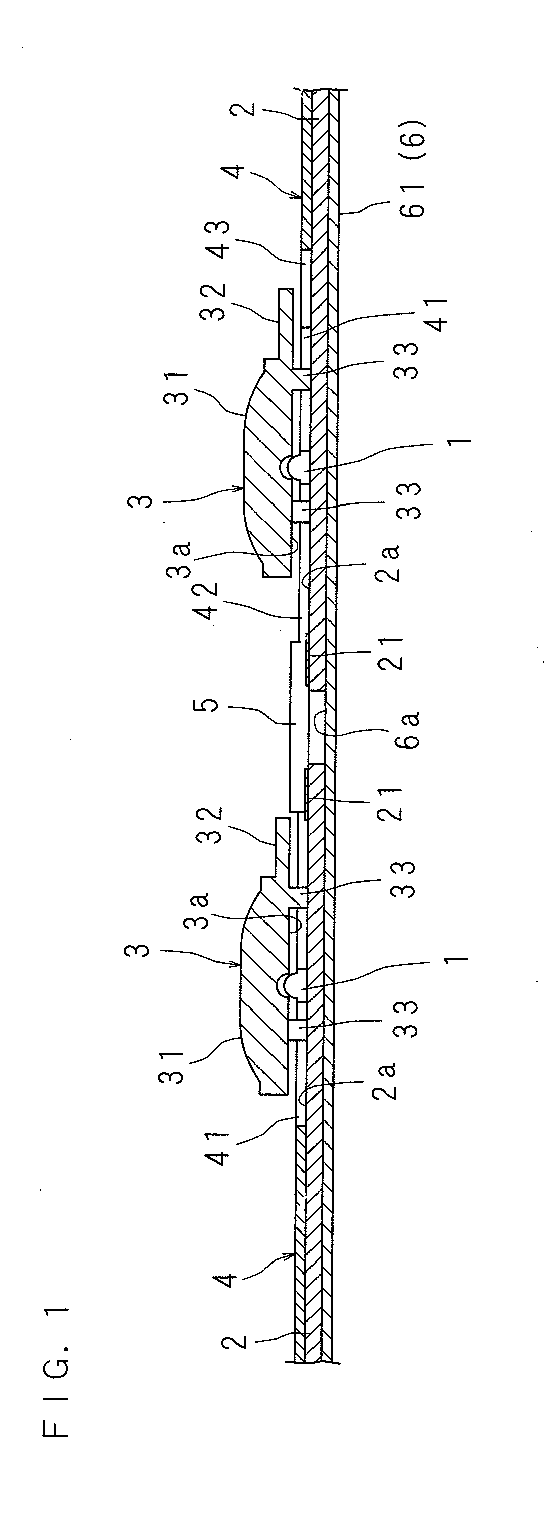
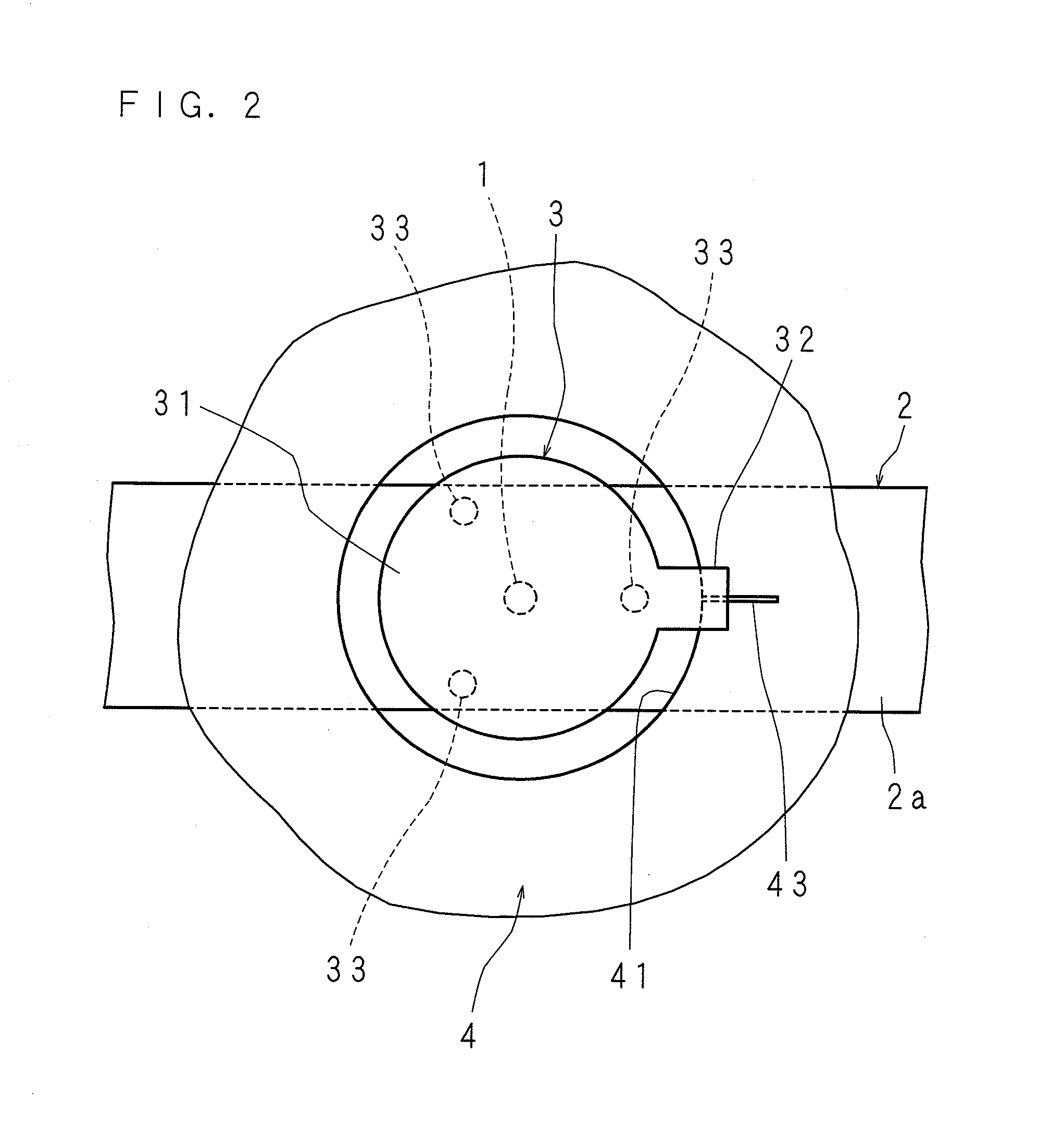
[0049]FIG. 1 is a sectional view illustrating the configuration of a light source device, where a part is enlarged. FIG. 2 is an enlarged plan view illustrating the configuration of a main part. FIG. 3 is a schematic perspective view of a light source device, where a part is disassembled. FIG. 4 is a plan view of a light source device, where a part is omitted. FIG. 5 is a perspective view illustrating the configuration of a LED board to which a lens is attached.

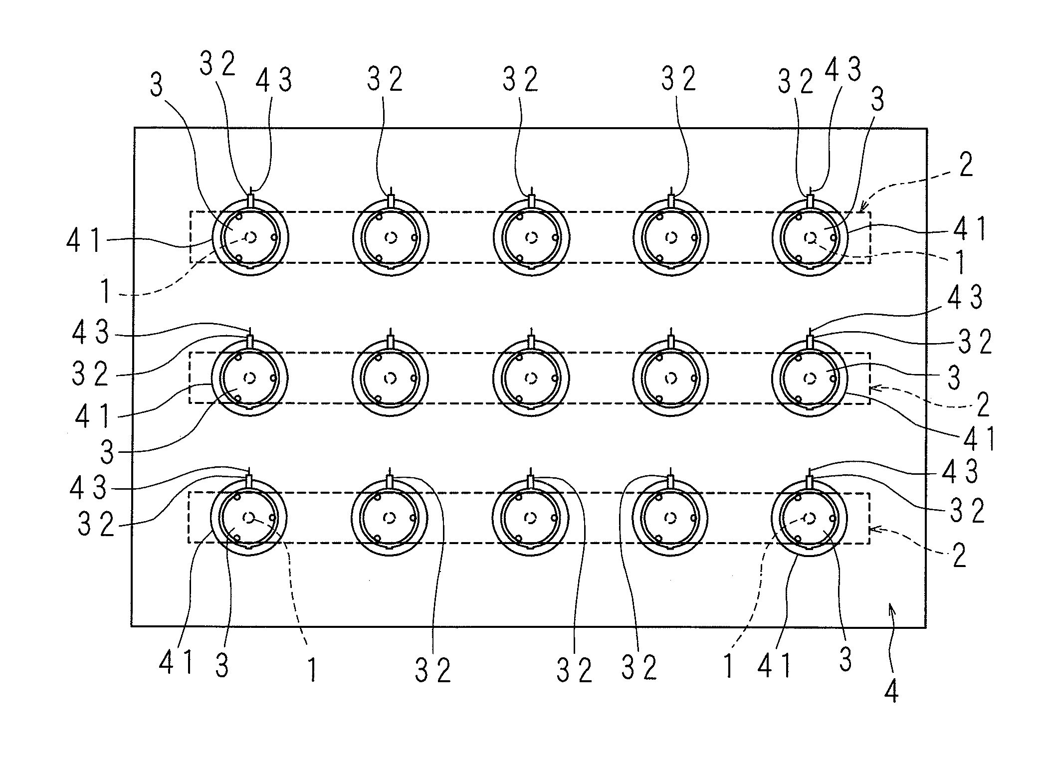
[0050]The light source device illustrated in the figures is attached to the rear side of a display part in a flat-screen display device provided with a display part having a display surface on the front side and having an approximately rectangular parallelepiped shape. The light source device has: a plurality of LEDs 1 aligned in a matrix pattern; a plurality of LED boards 2 in which the LEDs 1 are mounted on a surface 2a and which are aligned in a grid pattern; a plurality of lenses 3 attached to the surface 2a of the LED bo...

embodiment 2

[0068]FIG. 8 is an enlarged plan view illustrating another configuration of the main part of a light source device. FIG. 9 is an enlarged sectional view illustrating another configuration of the main part of a light source device. FIG. 10 is an explanation diagram illustrating a state that the reflecting sheet 4 is under assembling.

[0069]In this light source device, in place of a configuration that the slit 43 is provided at the edge of the through hole 41 in the reflecting sheet 4, the through hole 41 is formed in a round shape of a slightly larger diameter than the lens 3 with the convex portion 32. By virtue of this, when the reflecting sheet 4 is to be placed opposite to the surface 2a of the LED board 2, the transparent part 31 and the convex portion 32 are fit into the through hole 41 and then the reflecting sheet 4 is moved in a direction along the LED board 2 in a state that the reflecting sheet 4 is placed on the surface 2a. Then, the through hole 41 peripheral edge of the ...

embodiment 3

[0072]FIG. 11 is a schematic plan view illustrating another configuration of the main part of a light source device. In this light source device, in place of a configuration that the lenses 3 are aligned such that the convex portions 32 serving as restricting means are oriented in the same direction, the lenses 3 are aligned such that the convex portions 32 are oriented in different directions, that is, the convex portions 32 are oriented toward the four sides of the plate part 61 having an approximate rectangular shape.

[0073]In the configuration that the plurality of LED boards 2 having a strip shape are disposed in parallel to each other in the plate part 61 having an approximate rectangular shape, in each lens 3 attached to the LED board 2 disposed on one longer-side side of the plate part 61, the convex portions 32 are oriented toward the one longer side. In each lens 3 attached to the LED board 2 disposed on the other longer-side side of the plate part 61, the convex portions 3...


PUM


Abstract

A light source device includes a circuit board having a LED mounted on a surface, a lens attached to the surface so as to diffuse light emitted from the LED, a reflecting sheet having a through hole in the inside of which the lens is disposed and reflecting light emitted from the LED at an opposite side of the surface, and a restricting member which is disposed at one of an edge of the through hole in the reflecting sheet and the lens, and restricts a deviation of the reflecting sheet in a direction departing from the surface.

Description

CROSS-REFERENCE TO RELATED APPLICATION[0001]This application is the national phase under 35 U.S.C. §371 of PCT International Application No. PCT / JP2010 / 058501 filed in Japan on May 5, 2010, the entire contents of which are hereby incorporated by reference.BACKGROUND[0002]1. Technical Field[0003]The present invention relates to: a light source device provided with a circuit board on which a LED is mounted; and a display device provided with this light source device.[0004]2. Description of the Related Art[0005]In a display device such a television set, a light source device is disposed on the rear side of a display part having, on the front side, a display surface displaying an image.[0006]A light source device has, for example: a LED board having a plurality of LEDs mounted on one surface; a lens accommodating the LED and diffuses light emitted from the LED; and a lens cover that has a through hole into which the lens is inserted and that holds the lens on the LED board. Then, a refl...

Claims


Application Information

Patent Timeline
Patent Type & Authority Applications(United States)
IPC IPC(8): F21V13/04
CPCG09F9/33H01L25/0753H01L33/58H05K2201/2054H05K1/142H05K3/0061H05K2201/10106H01L33/60H01L2924/0002H01L2924/00
Inventor TAKEUCHI, HIDETO
Owner SHARP KK
Why Eureka
Try Eureka