Radio wave-transmitting decorative film and decorative member using same

a technology of decorative film and radio wave, applied in the field of radio wave-transmitting decorative, can solve the problems of low productivity, tin is prone to oxidation, low product quality, etc., and achieve the effects of excellent stretch moldability, low cost, and not easily disappearing

Active Publication Date: 2012-03-15
SHIN-ETSU POLYMER CO LTD
View PDF12 Cites 11 Cited by
  • Summary
  • Abstract
  • Description
  • Claims
  • Application Information

AI Technical Summary

Benefits of technology

[0026]The radio wave-transmitting decorative film of the invention has radio wave transmissibility, a mirror-like metallic gloss which does not easily disappear, excellent stretch moldability, and low cost.
[0027]The decorative member of the invention has radio wave transmissibility, a mirror-like metallic gloss which does not easily disappear, an excellent external appearance in a portion where the decorative film of the corner portion is stretched, and low cost.

Problems solved by technology

(iv) The frequency of radio waves used in communication devices (wireless PAN such as Bluetooth, UWB, and ZigBee) has been shifting to a high frequency range of from millimeter waves to microwaves, at which radio waves are readily affected by the decorative members, and thus these devices are prone to functional disorders.
Therefore, as to whether a product using the decorative film of (1) does not impede the straightness of the radio waves, or other disorders do not occur, all of the products using the decorative film are required to be inspected, and therefore it has a low productivity.
In addition, tin is prone to oxidation, chlorination, or the like, as a result of which the metallic gloss thereof is lost over time.
On the other hand, indium is not readily available and highly expensive.
The decorative film of (2) has a low productivity and the high cost of a laminated film.
In addition, the heating stretch moldability is deteriorated and therefore the decorative film cannot be formed into a desirable shape.
Further, through hot forming, the refractive index of the decorative film and the balance of the respective layers are changed, and therefore a loss of metallic gloss occurs.

Method used


Image

  • Radio wave-transmitting decorative film and decorative member using same
  • Radio wave-transmitting decorative film and decorative member using same
  • Radio wave-transmitting decorative film and decorative member using same

Examples


first embodiment

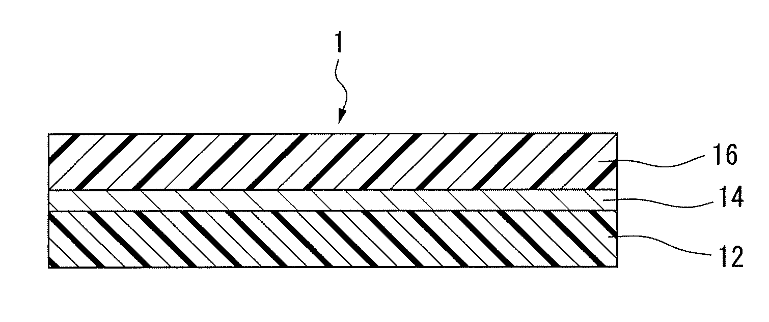
[0044]FIG. 1 is a cross sectional view showing an example of the radio wave transmitting decorative film (hereinafter, simply referred to as decorative film) according to the present invention. The decorative film 1 includes a first polymer film 12, a light-reflecting layer 14 provided on the surface of the first polymer film 12, and a second polymer film 16 provided on the surface of the light-reflecting layer 14.

[0045]Polymer Film

[0046]A first polymer film 12 and a second polymer film 16 (hereinafter, referred to as a polymer film) are films having radio wave transmissibility.

[0047]At least one of the first polymer film 12 and second polymer film 16 is required to be a transparent film. The transmittance to visible light of the transparent polymer film is preferably 80% or more.

[0048]The thickness of the polymer film is preferably 10 to 100 μm from the viewpoint of moldability of the decorative film 1. The thickness of the decorative film is preferably 20 to 150 μm.

[0049]Examples ...

second embodiment

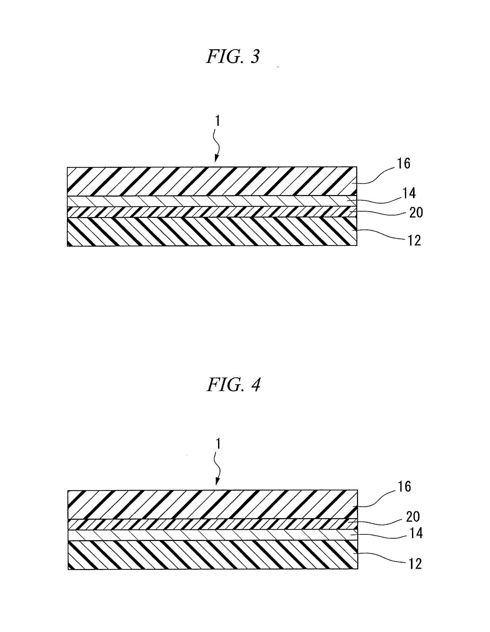
[0082]FIG. 3 is a cross sectional view showing another example of a radio wave transmitting decorative film according to the present invention. A decorative film 1 includes a first polymer film 12, an adhesion promoting layer 20 provided on the surface of the first polymer film 12, a light-reflecting layer 14 provided on the surface of the adhesion promoting layer 20, and a second polymer film 16 provided on the surface of the light-reflecting layer 14.

[0083]In the second embodiment, the same configurations as in the first embodiment have the same references, the description of which will be omitted.

[0084]Adhesion Promoting Layer

[0085]In order to improve the adhesiveness between the polymer film and the light-reflecting layer 14, the adhesion promoting layer 20 is previously formed on the surface of the polymer film before forming the light-reflecting layer 14 or on the surface of the light-reflecting layer 14 after forming the light-reflecting layer 14.

[0086]The materials for the a...

third embodiment

[0099]FIG. 4 is a cross sectional view showing another example of the radio wave-transmitting decorative film of the invention. The decorative film 1 includes a first polymer film 12, a light-reflecting layer 14 provided on the surface of the first polymer film 12, an adhesion promoting layer 20 provided on the surface of the light-reflecting layer 14, and a second polymer film 16 provided on the surface of the adhesion promoting layer 20.

[0100]In the third embodiment, the same configurations as the first embodiment and the second embodiment have the same references, the description of which will be omitted.


PUM

PropertyMeasurementUnit
wavelengthaaaaaaaaaa

Abstract

Disclosed are a low-cost radio wave-transmitting decorative film which has excellent stretch moldability, radio wave transmissibility, and mirror-like metallic gloss that does not easily disappear, and a decorative member employing the radio wave-transmitting decorative film. Specifically disclosed are a decorative film which includes a first polymer film, a second polymer film, and a light-reflecting layer which is arranged between the polymer films and formed by the physical vapor deposition of an alloy of silicon and a metal, and a decorative member in which the decorative film is provided on the surface of a base.

Description

TECHNICAL FIELD[0001]The present invention relates to a radio wave-transmitting decorative film having metallic gloss and a decorative member using the same.[0002]Priority is claimed on Japanese Patent Application No. 2009-64568, filed Mar. 17, 2009, the content of which is incorporated herein by reference.BACKGROUND ART[0003]From the viewpoint of design properties, metallic decorative members, in particular, decorative members having a mirror-like metallic gloss have been widely used in the casing of a mobile phone; the button of a switch; the casing of a watch; and the radiator grill, bumper, panel or the like of a vehicle.[0004]As such decorative members, a decorative member that transmits radio waves (microwaves or the like) without adversely affecting the radio waves has been required for the following reasons:[0005](i) An antenna for transmitting and receiving radio waves is disposed inside the casing of a mobile phone.[0006](ii) An antenna for receiving radio waves is dispose...

Claims


Application Information

Patent Timeline
Patent Type & Authority Applications(United States)
IPC IPC(8): B32B15/08
CPCB32B27/08B32B2250/24C23C14/20B32B2255/205B32B2307/416B32B2255/10B32B7/12B32B27/302B32B27/304B32B27/306B32B27/308B32B27/32B32B27/325B32B27/36B32B27/365B32B27/40B32B2307/20B32B2307/406B32B2307/412B32B2307/732B32B2451/00
Inventor KAWAGUCHI, TOSHIYUKITAHARA, KAZUTOKISAGA, TSUTOMU
Owner SHIN-ETSU POLYMER CO LTD
Why Eureka
Try Eureka