Lead-acid battery and method for manufacturing current collector for lead-acid battery
a lead-acid battery and current collector technology, applied in the field of lead-acid batteries, can solve the problems of inconvenient breaking increasing corrosion, and increasing the risk of damage to the lead-acid battery, so as to reduce the bending strength of the width of the current collecting lug parts is limited, and the effect of easy formation
- Summary
- Abstract
- Description
- Claims
- Application Information
AI Technical Summary
Benefits of technology
Problems solved by technology
Method used
Image
Examples
examples
[0045]Specific examples of the lead-acid battery according to the present invention will be described below using as an example a lead-acid battery that uses a plate in which an active material is held on a current collector formed by the expanding process. Lead-acid batteries according to Conventional Example and Reference Example fabricated for comparison will also be described.
examples 1 to 9
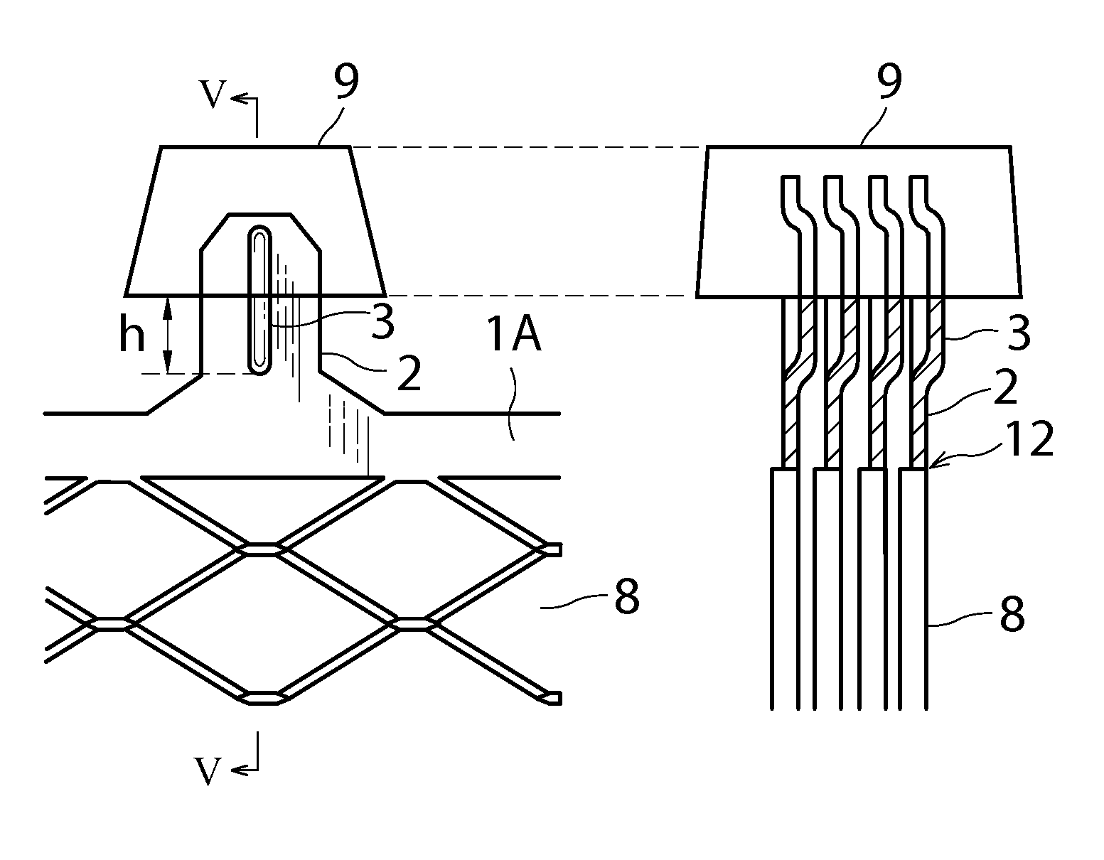
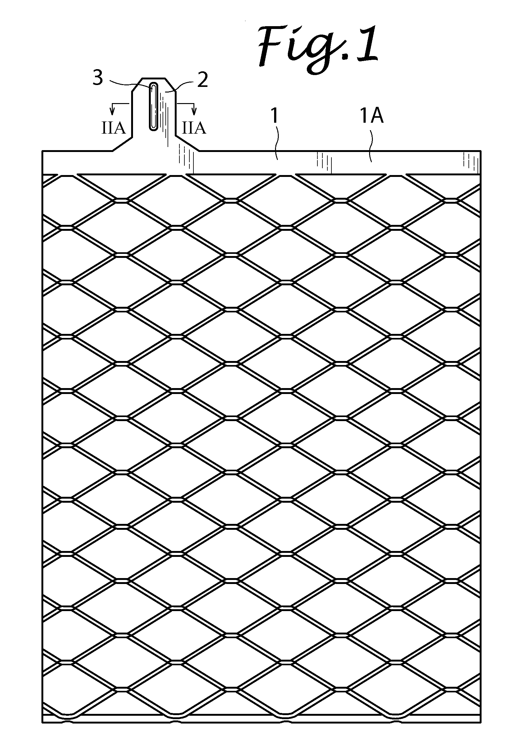
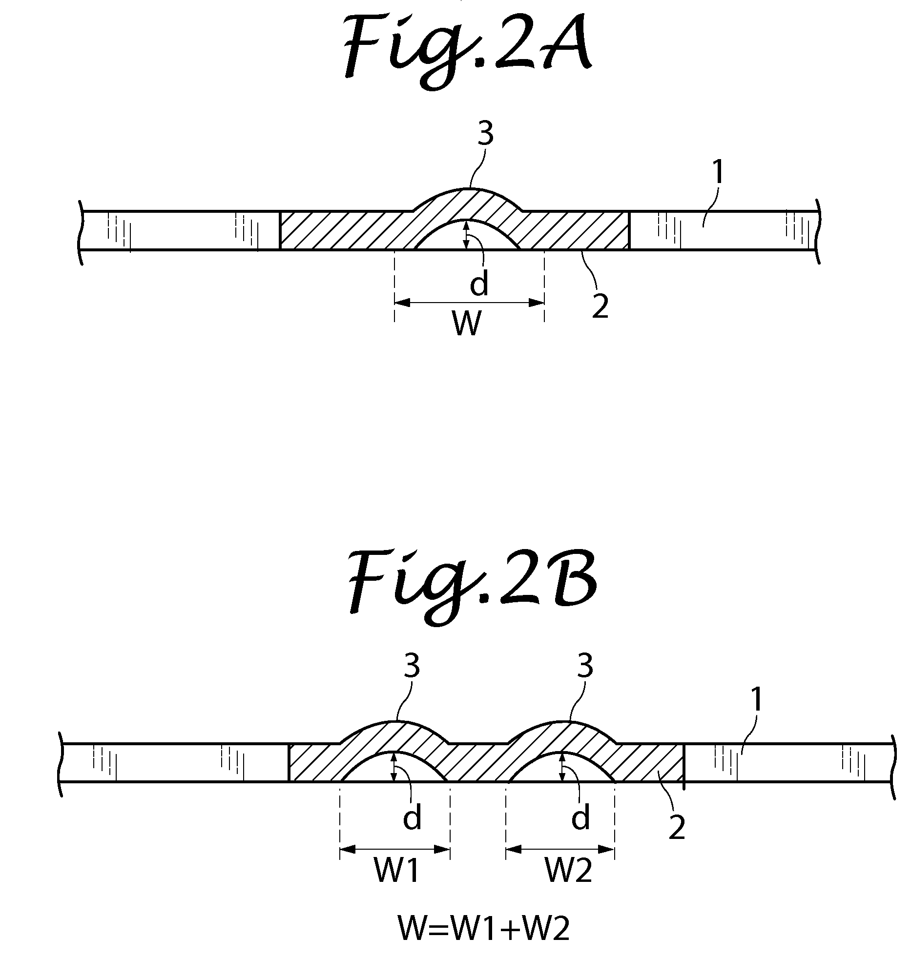
[0046]A lead alloy sheet with a thickness of 0.9 mm manufactured by cold rolling was expanded to prepare a current collector 1 unitarily formed with a current collecting lug part 2. The current collecting lug part 2 was formed with an elongated protrusion 3 with a length of 12 mm by the method described above in relation to the embodiment of the present invention. The protrusion 3 was formed to protrude on one surface of the current collecting lug part 2 with a width of 10 mm in correspondence with an elongated depression 30 formed in the other surface of the current collecting lug part 2 at a position corresponding to the protrusion 3. The width of the depression 30 (dimension w in FIG. 2A) was set to 3 mm, and the depth of the depression 30 (dimension d in FIG. 2A) was varied in the respective examples as shown in Table 1. Using the above respective types of current collectors as positive plates, positive plates and negative plates were alternately layered one by one with a microp...
examples 10 to 18
[0047]Examples 10 to 18 are different from Examples 1 to 9 described above in that two protrusions 3 were juxtaposed. The distance between the bottoms of the depressions 30, 30 was set to 4 mm. The width w of the depressions 30, 30 (the sum of the widths w1 and w2 of the depressions 30, 30 in FIG. 2B) was set to 3 mm. The measurement results of the bending strength of the current collecting lug part 2 of the positive plate after forming the strap 9 are shown in Table 1.
TABLE 1EXAMPLE123456789DEPRESSION0.250.50.751.01.151.221.251.321.4DEPTH (mm)BENDING8286.592102113123130160300STRENGTH (N)EXAMPLE101112131415161718DEPRESSION0.250.50.751.01.151.221.251.321.4DEPTH (mm)BENDING8493104124146166180240520STRENGTH (N)
PUM
| Property | Measurement | Unit |
|---|---|---|
| length | aaaaa | aaaaa |
| depth | aaaaa | aaaaa |
| temperature | aaaaa | aaaaa |
Abstract
Description
Claims
Application Information
 - R&D
- Intellectual Property
- Life Sciences
- Materials
- Tech Scout
- Unparalleled Data Quality
- Higher Quality Content
- 60% Fewer Hallucinations
Browse by: Latest US Patents, China's latest patents, Technical Efficacy Thesaurus, Application Domain, Technology Topic, Popular Technical Reports.
© 2025 PatSnap. All rights reserved.Legal|Privacy policy|Modern Slavery Act Transparency Statement|Sitemap|About US| Contact US: help@patsnap.com


