System and methods for automatic power management of remote electronic devices using a mobile device

Inactive Publication Date: 2012-03-15
CISCO TECH INC
View PDF12 Cites 182 Cited by
  • Summary
  • Abstract
  • Description
  • Claims
  • Application Information

AI Technical Summary

Benefits of technology

[0012]Briefly described, and according to one embodiment, aspects of the present disclosure generally relate to systems and methods for managing and monitoring (in real time as well as in non-real time) a plurality of electrical and/or electronic devices remotely via a consolidated system without the need for installing additional software on individual devices. According to one aspect of the present disclosure, and described in greater detail herein, an energy management system (EMS) is easil

Problems solved by technology

However, as will be understood and appreciated, deploying energy efficient devices can involve an added cost burden to the device purchasers.
This additional cost is largely due to the fact that such devices are manufactured with specialized electrical components that are technologically advanced and thereby consume less power, but are also more expensive than common, less-technically-advanced devices.
Consequently, large enterprises and organizations that wish to achieve energy efficiency through a full-scale deployment of energy efficient devices will face an enormous cost upfront, and it may take a substantial amount of time to recoup the upfront cost of the devices through the cost savings they provide.
Furthermore, even if such devices are deployed, this would be highly ineffective and inconvenient from an operational perspective as a large number of pre-existing devices that were fully functional would need to be replaced, transitioned, and/or potentially discarded.
These racks and servers typically need to be monitored for consumed electrical power, and if one of these components fails or produces excess heat due to prolonged operation, it may need to be turned off.
In either case, the cost of installation (and subsequent maintenance a

Method used


Image

  • System and methods for automatic power management of remote electronic devices using a mobile device
  • System and methods for automatic power management of remote electronic devices using a mobile device
  • System and methods for automatic power management of remote electronic devices using a mobile device

Examples


Embodiment Construction

[0049]Prior to a detailed description of the disclosure, the following definitions are provided as an aid to understanding the subject matter and terminology of aspects of the present systems and methods, are exemplary, and not necessarily limiting of the aspects of the systems and methods, which are expressed in the claims.

DEFINITIONS / GLOSSARY

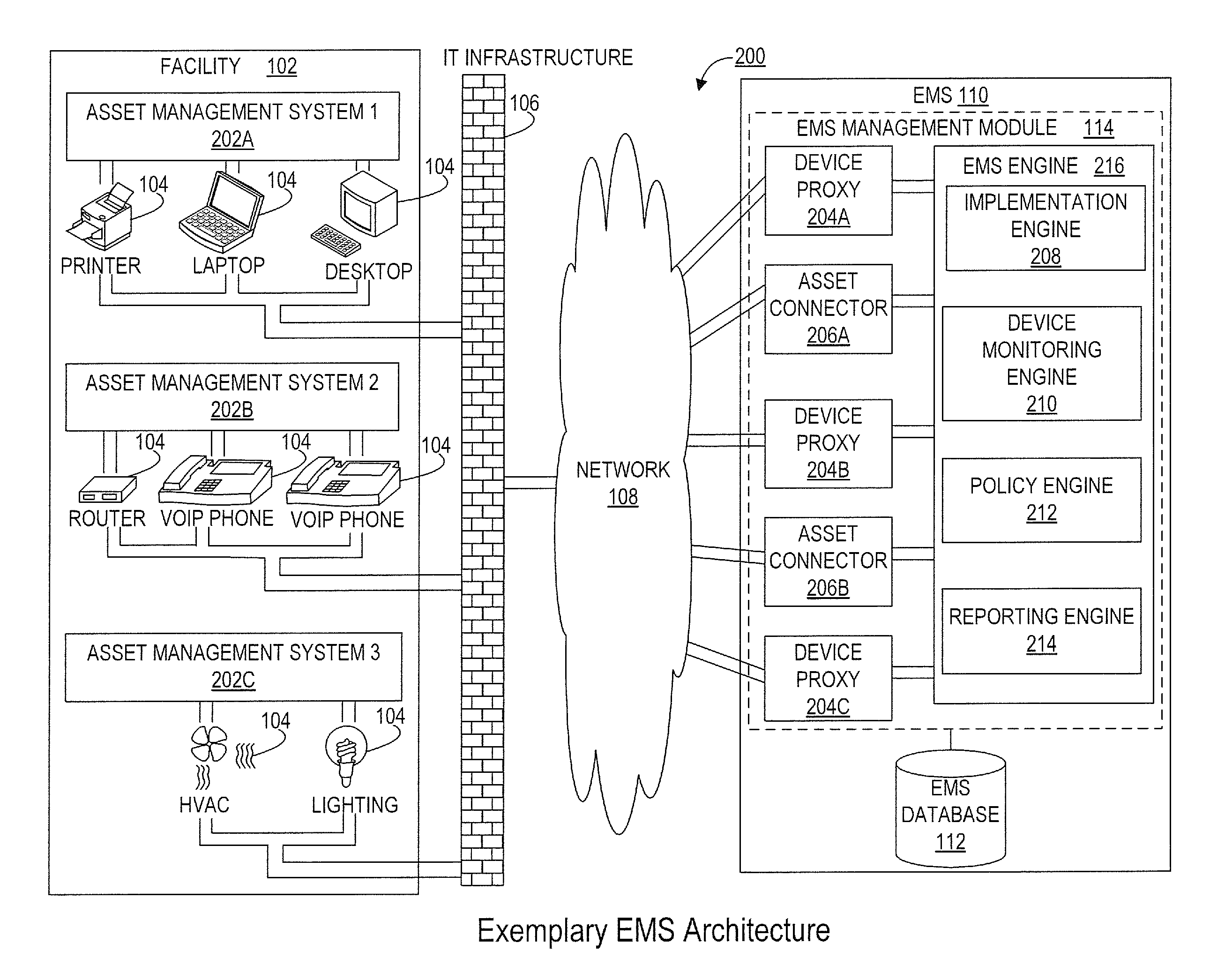
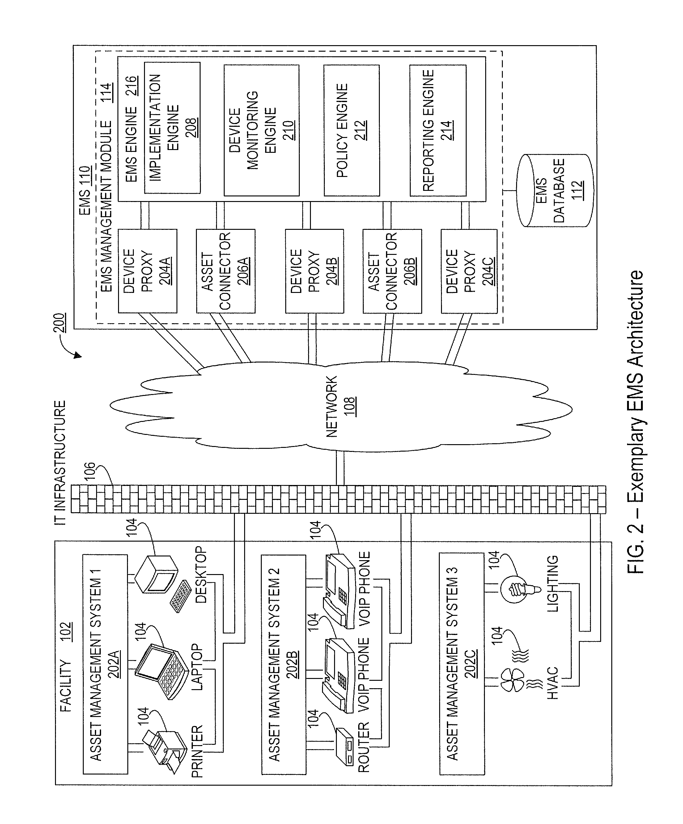
[0050]Action: an activity or task that is executed under the direction of an energy management system (EMS) in connection with performing energy efficiency management or monitoring of an asset. Examples of actions performed on assets include, but are not limited to, changing the power state of the asset, viz. from power on mode to hibernate mode, notifying an EMS administrator via email regarding the change of the power state of an asset, running a script written by a programmer, etc.

[0051]Active Region: a geographic, physical, spatial, or temporal area that, when a user's mobile device is contained therein, triggers an action with respect to ...


PUM


Abstract

Systems and methods for managing and monitoring a plurality of disparate electrical and/or electronic devices located at various geographically distributed facilities remotely on the basis of an instantaneous location of a user's mobile device that is associated with one or more electrical and/or electronic devices. Remote management of these devices involve transmitting information corresponding to a current location of a user's mobile device that will be managing the devices, without the need for installing additional software on the devices. An energy management system installed within an organization's infrastructure communicates with users' mobile devices and executes power management commands on the electrical and/or electronic devices, for purposes of monitoring and managing several operational aspects related to such devices. Such power management commands can be on-demand dynamic commands provided by a user's mobile device, or predefined commands stored in the energy management system.

Description

CROSS-REFERENCE TO RELATED APPLICATIONS[0001]This application is a continuation-in-part application, and claims the benefit of and priority under 35 U.S.C. §120 to U.S. patent application Ser. No. 13 / 092,670 filed Apr. 22, 2011 and entitled “Systems and Methods for Sustainable Energy Management, Monitoring, and Control of Electronic Devices.” In addition, the present application also claims benefit of and priority under 35 U.S.C. §119(e) of U.S. Provisional Patent Application No. 61 / 382,764, filed Sep. 14, 2010, and entitled “Automatic Power Management of Remote Electronic Devices Using a Mobile Device.” Both the above-referenced applications are hereby incorporated by reference as if set forth herein in their entireties.TECHNICAL FIELD[0002]The present systems and methods relate generally to remote energy management of electronic devices, and more particularly to systems and methods that provide the ability to remotely control the energy consumed by network-connected devices and sy...

Claims


Application Information

Patent Timeline
IPC IPC(8): G06F1/26
CPCG06F1/3203Y02B60/1267H04W4/021H04W4/04H04L67/125Y02B70/3225Y02B70/325Y02B70/3266Y02B90/2653Y04S20/222Y04S20/228Y04S20/242Y04S40/126H02J3/14H02J13/0075H02J13/0086H02J2003/143H04L12/2825Y04S40/18H04W4/38H02J2310/14H02J2310/16H02J13/00024H02J13/00026H02J13/00004H02J13/00028Y02B70/30Y02D10/00Y02B90/20Y02D30/70Y04S20/20
Inventor SEEBER, RENEBRUNNER, JOSEFDAVIDSON, MARK
Owner CISCO TECH INC
Why Eureka
Try Eureka