Ring-shaped or plate-like element and method for producing same

a plate-like element and ring-type technology, applied in the direction of forging/pressing/hammering equipment, lighting and heating equipment, handling devices, etc., can solve the problems of weakening the glazing, large amount of material waste, etc., and achieve the effect of reducing the thickness of the plate-like element and being easy to produ

Active Publication Date: 2012-03-22
SCHOTT AG
View PDF11 Cites 14 Cited by
  • Summary
  • Abstract
  • Description
  • Claims
  • Application Information

AI Technical Summary

Benefits of technology

[0011]The present invention provides a plate-like element which forms the base body for a metal-sealing material-feedthrough that includes a feedthrough opening which is located substantially in the center of the plate-like element, whereby the plate-like element has a thickness (D) and whereby a relief region is provided in the region of the feedthrough opening in the plate-like element. The thickness of the plate-like element is reduced in the area of the feedthrough opening by the relief region, for example so that the feedthrough opening can be punched out through the ring-shaped or plate-like element in the area of the relief region. Punching out the opening provides a base body which is especially easy to produce.
[0013]According to the present invention, the thickness (D) of the ring-shaped or plate-like element may be reduced by the relief region by between 20% and 60%, for example between 30% and 50%.
[0037]An additional advantage of the inventive ring-shaped or plate-like element is that with the described production method no, or at most very little, material waste occurs. Therefore, it can be produced very efficiently.
[0041]It has been shown that the relief region not only enables the punchability of the feedthrough opening. The reduction in thickness of the ring-shaped or plate-like element in the relief region can also facilitate a local deflection of the element during pressurization, for example through the explosion pressure. The inventors recognized that this deflection does not have to be negative, but that instead the extraction resistance of the sealing material in the feedthrough opening can even be increased, especially if the feedthrough opening possesses the described means to prevent the relative movement.
[0043]Moreover, the reduction of the thickness of the ring-shaped or plate-like element in the relief region can improve the weldability of the element with additional elements, for example with the cover cap of igniters or pressure sensors. The reduction in thickness of the element in the relief region causes the element to have a peripheral ring-shaped area which is thicker compared to the relief region. When producing, for example, an ignition device or a pressure sensor a metal pin is normally glazed into the feedthrough opening on the ring-shaped or plate-like element. Likewise, a second conductor can be connected to the bottom of the element. A cover cap is normally welded to the outer circumference of the element. When welding on the cover cap, heat is inevitably introduced into the element. Care must be taken here that the glass as the sealing material is not damaged. The peripheral area which is qualified by the relief region has a larger surface which can again radiate the introduced heat, thereby reducing the temperature load on the sealing material. This ring-shaped area therefore functions as a welding edge during the welding process. Due to the simplified weldability, rejects in further processing of the element into the end product can be reduced and the process stability increased.

Problems solved by technology

One disadvantage is that when punching a strip stock, for example sheet metal of the base body, a great amount of material waste occurs.
Especially in metal-sealing material-feedthroughs with two metal pins and an off-center opening the problem arises that the off-center opening results in a weakening of the glazing.

Method used


Image

  • Ring-shaped or plate-like element and method for producing same
  • Ring-shaped or plate-like element and method for producing same
  • Ring-shaped or plate-like element and method for producing same

Examples


Embodiment Construction

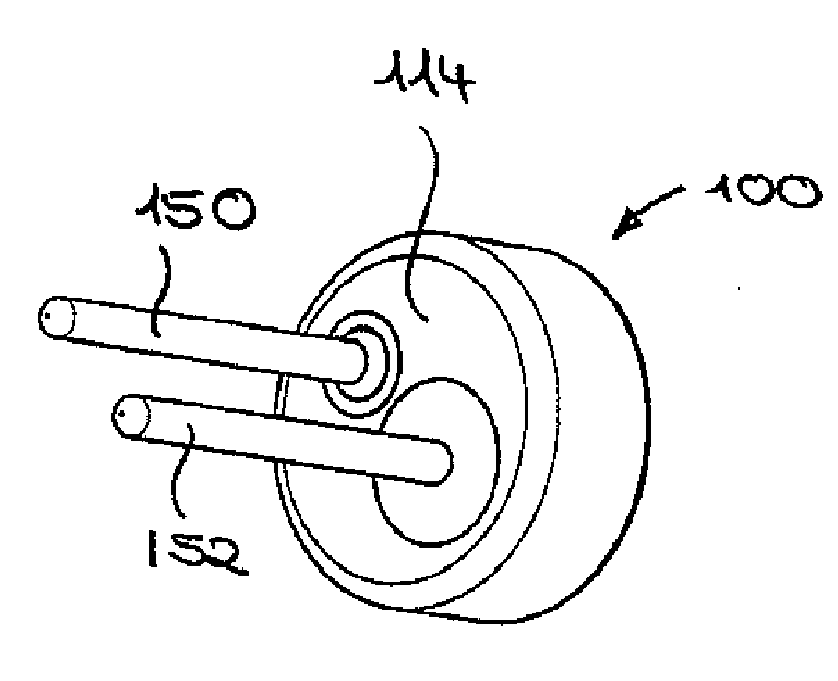
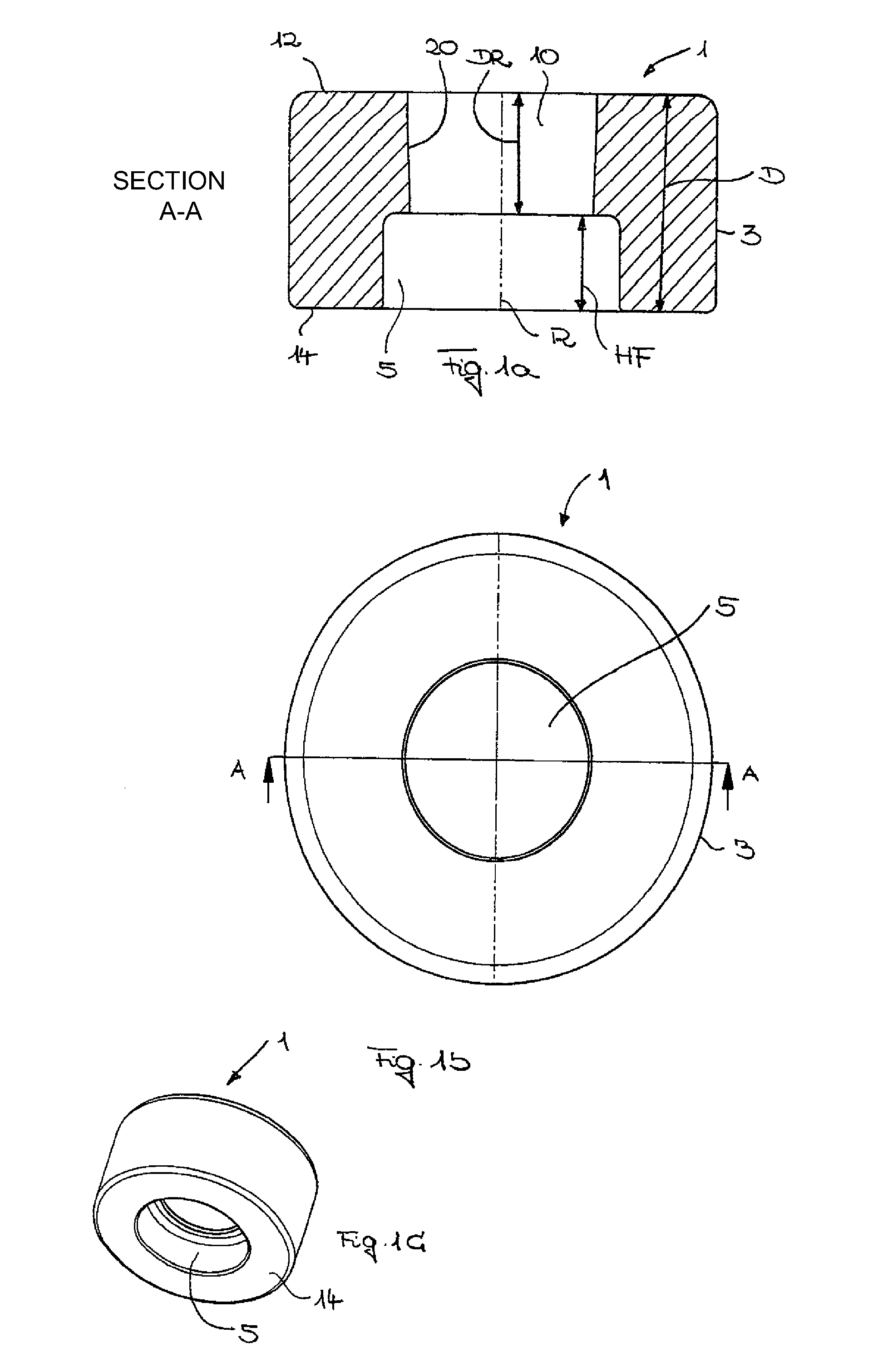
[0054]Referring now to the drawings, and more particularly to FIGS. 1a-1c, there is shown a ring-shaped or plate-like formation or element according to the present invention which essentially is utilized as the base body for a metal-sealing material-feedthrough. As shown in the top view in FIG. 1b, ring-shaped or plate-like element 1 has essentially circular outer contour 3. Ring-shaped or plate-like body 1 is produced, for example, by a reshaping process, such as a cold-forming process, for example from a wire. Hereby, a piece is first cut from the wire and is subsequently transformed through a reshaping process, for example through compression into the spherical or circular form illustrated in FIG. 1b in a top view and FIG. 1c three-dimensionally from backside 14.

[0055]Following this, relief region 5 is provided into reshaped component 1 by means of a punch. When providing the relief region with a punch the reshaped material surrounds the punch.

[0056]The sequence of the process st...


PUM

PropertyMeasurementUnit
thicknessaaaaaaaaaa
thicknessaaaaaaaaaa
thicknessaaaaaaaaaa

Abstract

A ring-shaped or plate-like element, in particular for a metal-sealing material-feedthrough, for example for devices which are subjected to high pressures, such as igniters for airbags or belt tensioning devices, includes a feedthrough opening, whereby the feedthrough opening is located substantially in the center of the ring-shaped or plate-like element and whereby the ring-shaped or plate-like element has a thickness. The ring-shaped or plate-like element has a relief region in the area of the feedthrough opening. Further, the ring-shaped or plate-like element in the relief region has at least one thickness which is reduced by the height of the relief region and which is selected so that the feedthrough opening can be punched out of the ring-shaped or plate like element having the reducing thickness.

Description

BACKGROUND OF THE INVENTION[0001]1. Field of the Invention[0002]The present invention relates to a ring-shaped or plate-like element, in particular for a metal-sealing material-feedthrough, in particular for devices which are subjected to high pressures, for example igniters for airbags or belt tensioning devices, as well as a method of utilization of such a metal-sealing material-feedthrough.[0003]2. Description of the Related Art[0004]Metal-sealing material-feedthroughs are already known in various forms from the current state of the art. Metal-sealing material-feedthroughs are to be understood to be vacuum-tight fusions of sealing materials, especially glasses, glass ceramics or synthetics in metals. The metals function hereby as conductors. We refer you in this context to representative documentation U.S. Pat. No. 5,345,872 and U.S. Pat. No. 3,274,937. Feedthroughs of this type are common in electronics and in electrical engineering. The material used for sealing, especially gla...

Claims


Application Information

Patent Timeline
Patent Type & Authority Applications(United States)
IPC IPC(8): F23Q13/00B60R21/26B21D43/28
CPCF42B3/198F42B3/103F42B3/195Y10T29/49908B21D28/02B60R21/20B60R22/12F42C19/12H01B17/30H02G3/26
Inventor HARTL, HELMUTPFEIFFER, THOMAS
Owner SCHOTT AG
Why Eureka
Try Eureka