Engine that is Equipped with Variable Valve Device

a variable valve and valve device technology, applied in the field of engines, can solve the problems of difficult to simply or compactly constitute the variable valve train and the hydraulic pressure lash adjuster in a restricted space, and achieve the effect of reducing the weight of components and small overall structur

Inactive Publication Date: 2012-03-22
HYUNDAI MOTOR CO LTD
View PDF4 Cites 13 Cited by
  • Summary
  • Abstract
  • Description
  • Claims
  • Application Information

AI Technical Summary

Benefits of technology

[0016]As stated above, in the engine that may be provided with a variable valve device according to the present invention, a variable valve device may be realized in the hydraulic pressure lash adjuster such that the overall structure becomes small and the component weight may be reduced.

Problems solved by technology

Meanwhile, a hydraulic pressure lash adjuster (HLA) is used so as to reduce a gap between a valve and a swing arm in a variable valve train, but it is difficult to simply or compactly constitute the variable valve train and the hydraulic pressure lash adjuster in a restricted space.

Method used


Image

  • Engine that is Equipped with Variable Valve Device
  • Engine that is Equipped with Variable Valve Device
  • Engine that is Equipped with Variable Valve Device

Examples


Embodiment Construction

[0023]Reference will now be made in detail to various embodiments of the present invention(s), examples of which are illustrated in the accompanying drawings and described below. While the invention(s) will be described in conjunction with exemplary embodiments, it will be understood that present description is not intended to limit the invention(s) to those exemplary embodiments. On the contrary, the invention(s) is / are intended to cover not only the exemplary embodiments, but also various alternatives, modifications, equivalents and other embodiments, which may be included within the spirit and scope of the invention as defined by the appended claims.

[0024]An exemplary embodiment of the present invention will hereinafter be described in detail with reference to the accompanying drawings.

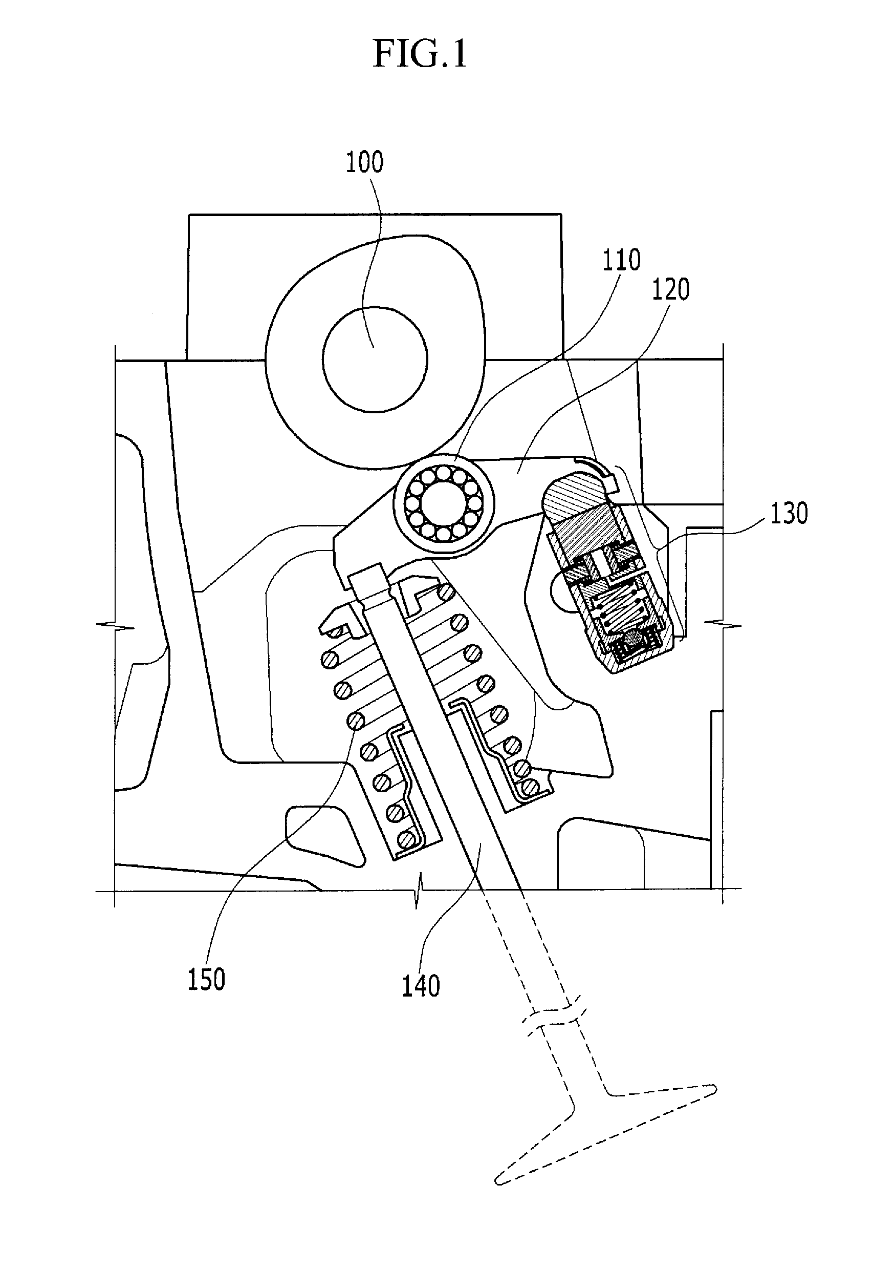
[0025]FIG. 1 is a schematic cross-sectional view of an engine that is provided with a variable valve device according to an exemplary embodiment of the present invention.

[0026]Referring to FIG. 1, ...


PUM


Abstract

An engine includes a hydraulic pressure lash adjuster (HLA) pivotally supporting an end of a swing arm and having a valve supporting the other end of the swing arm, wherein the hydraulic pressure lash adjuster includes a housing, a plunger of which one end portion thereof may be slidably inserted into the inside of the housing, the other end portion of which extends outwards and supports the end of the swing arm by selectively moving upwards or downwards in a length direction of the housing, a stopper pin slidably mounted in a chamber of the plunger so as to selectively lock the plunger to the housing such that the plunger cannot move in the housing, and a hydraulic pressure supply portion that selectively supplies one side of the stopper pin with a hydraulic pressure in the chamber of the plunger to move the stopper pin toward the housing.

Description

CROSS-REFERENCE TO RELATED APPLICATION[0001]The present application claims priority to Korean Patent Application No. 10-2010-0092697 filed in the Korean Intellectual Property Office Sep. 20, 2010, the entire contents of which is incorporated herein for all purposes by this reference.BACKGROUND OF THE INVENTION[0002]1. Field of the Invention[0003]The present invention relates to an engine that is provided with a variable valve device that variably controls a motion of a valve disposed at an intake port or an exhaust port of a combustion chamber so as to improve fuel efficiency.[0004]2. Description of Related Art[0005]Some means for varying the timing of valve actuation of internal combustion engines are very well known. Such means typically take the form of a camshaft, a rocker arm, or a finger follower so as to control the valve motion.[0006]A variable valve device is especially well known in spark ignited engines, in which it is an essential element of various schemes for improving...

Claims


Application Information

Patent Timeline
Patent Type & Authority Applications(United States)
IPC IPC(8): F01L1/34F01L1/14
CPCF01L13/0005F01L1/2405
Inventor LEE, YOUNGSOO
Owner HYUNDAI MOTOR CO LTD
Why Eureka
Try Eureka