
Line element

Inactive Publication Date: 2012-03-22
NORMA GERMANY GMBH
View PDF14 Cites 0 Cited by
  • Summary
  • Abstract
  • Description
  • Claims
  • Application Information

AI Technical Summary

Benefits of technology

[0009]Embodiments of the present invention reduce the risk of damage occurring when a fluid freezes.
[0011]A pressure-compensating space as it were is provided inside the housing, so that a pressure that is generated in the fluid line during the freezing of the fluid can escape into the annular space. A reduction in volume of the compressible medium thereby occurs. The fluid line itself is thereby decompressed. The annular space is prevented from completely filling with the fluid by way of the compressible medium in the liquid state of the fluid. A pressure exerted on the line element due to the freezing of the fluid is reduced so much through this embodiment that no damage to the fluid line or the line element occurs. In particular, pressure peaks are thereby reduced. The compressible medium should of course thereby retain its desired compressibility at the usual subfreezing temperatures. The line element is thus embodied or formed as a pressure-compensating element.
[0013]Preferably, the compressible medium is thereby formed by air enclosed in the housing. This air is located throughout the entire annular space before the line element is filled. When the fluid is introduced into the fluid lines, the fluid passes through the opening into the annular space. In this way, air contained in the annular space can escape through this opening. When the fluid line is filled so far that the opening is completely covered, the air still remaining in the annular space can no longer escape, since the housing is connected to the fluid line in a fluid-tight manner. This enclosed air then forms the compressible medium. This embodiment makes a very cost-effective production of the line element possible. Moreover, the fluid is not contaminated by the compressible medium.
[0014]In another preferred embodiment, the compressible medium is embodied as a foam, in particular, as a closed-pore foam. The annular space can then be embodied or formed completely by the foam. A compression of the foam occurs under pressure and thus a reduction of pressure in the fluid line. With a closed pore foam, absorption of the fluid does not occur thereby. Through this embodiment, the compressibility of the medium can be adjusted relatively well.
[0020]Preferably, the fluid line has on at least one end a connection geometry, in particular an insert region. The line element can then be connected to other line elements relatively easily. The connection geometry can thereby project axially out of the housing. Both ends of the fluid line can be embodied identically. If both ends of the fluid line are embodied or formed as an insert region, for example, which in each case projects axially out of the housing, the line element can be inserted as a connecting element between two hose ends. The hose ends are then simply guided via the insert region and optionally secured with the aid of hose clamps. The line element can also be supplemented subsequently relatively easily.

Problems solved by technology

In the case of fluid lines filled with liquid, there is the problem in particular with motor vehicles in winter that, with longer downtime of the motor vehicles, the fluid located in the lines can freeze.
The freezing of the liquids results in an increase in volume and thus a compressive load on the lines.
In the worst case, damage to the lines or damage to connecting elements of the lines can occur as a result.
However, heating cannot be maintained over a longer period in which a vehicle is left standing.
So freezing cannot be reliably prevented by heating.

Method used


Image

  • Line element
  • Line element

Examples


Embodiment Construction

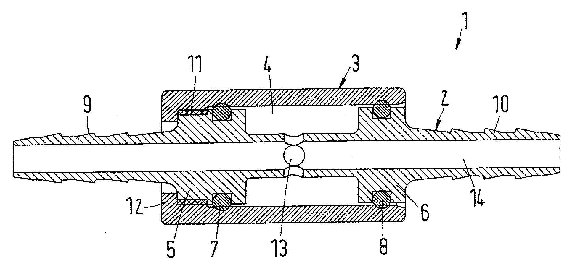
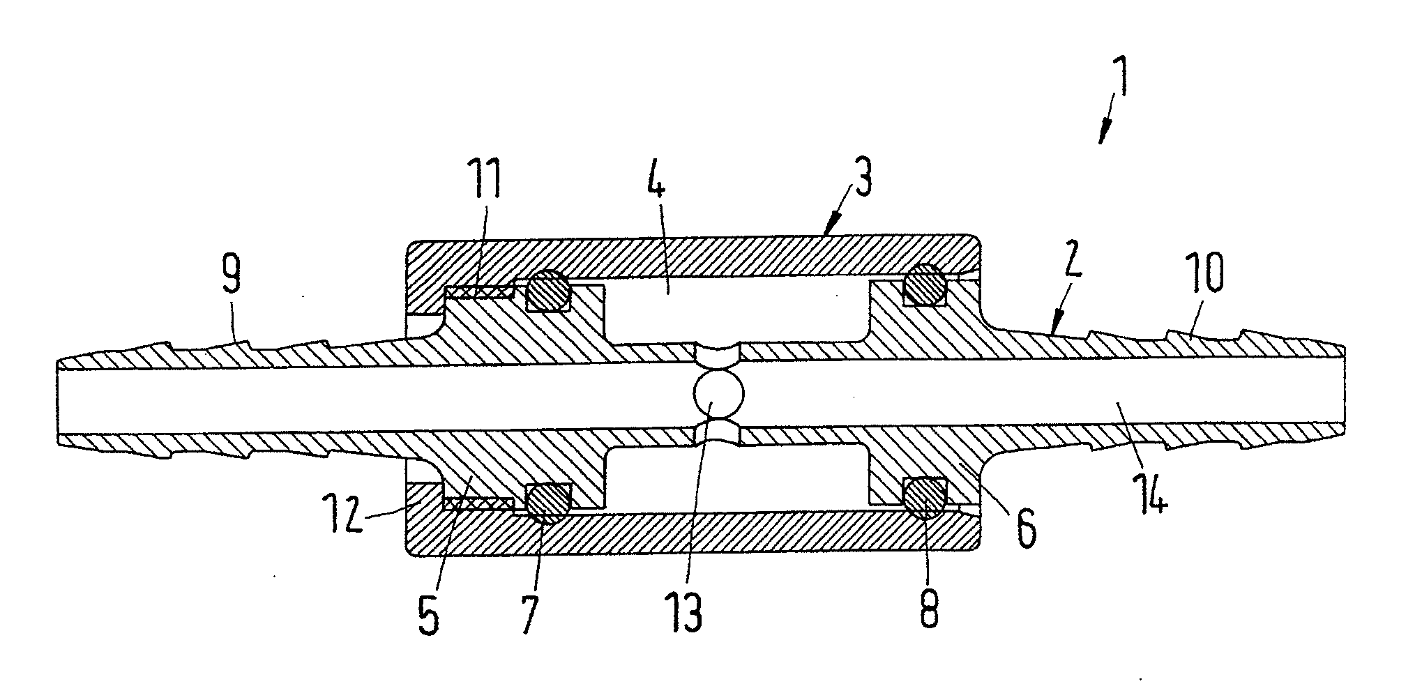
[0035]The particulars shown herein are by way of example and for purposes of illustrative discussion of the embodiments of the present invention only and are presented in the cause of providing what is believed to be the most useful and readily understood description of the principles and conceptual aspects of the present invention. In this regard, no attempt is made to show structural details of the present invention in more detail than is necessary for the fundamental understanding of the present invention, the description taken with the drawings making apparent to those skilled in the art how the several forms of the present invention may be embodied in practice.

[0036]In the FIGURE, a line element 1 with a fluid line 2 is shown. A housing 3 surrounds fluid line 2 in an annular manner, and an annular space 4 is embodied or formed between housing 3 and fluid line 2. Annular space 4 is limited in the axial direction by a respective ring flange 5, 6. The ring flanges 5, 6 are embodie...


PUM

PropertyMeasurementUnit
Forceaaaaaaaaaa
Circumferenceaaaaaaaaaa
Compressibilityaaaaaaaaaa

Abstract

Line element and method for forming a line element. The line element includes a fluid line, and a housing structured and arranged to surround the fluid line in a radially fluid-tight manner. An annular space is formed between the fluid line and the housing, which is filled at least in part with a compressible medium, and the fluid line has at least one opening inside the annular space.

Description

CROSS-REFERENCE TO RELATED APPLICATIONS[0001]The present application claims priority under 35 U.S.C. §119 of German Patent Application No. 10 2010 045 714.0, filed on Sep. 16, 2010, the disclosure of which is expressly incorporated by reference herein in its entirety.BACKGROUND OF THE INVENTION[0002]1. Field of the Invention[0003]The invention relates to a line element that has a fluid line and a housing.[0004]2. Discussion of Background Information[0005]Line elements of this type are used, for example, in motor vehicles for conveying engine coolant or as so-called urea lines. Lines that are used to supply urea, for example, in order to contribute to a clean combustion in diesel engines, are referred to as urea lines.[0006]In the case of fluid lines filled with liquid, there is the problem in particular with motor vehicles in winter that, with longer downtime of the motor vehicles, the fluid located in the lines can freeze. Urea, for example, freezes at −11° C.[0007]The freezing of ...

Claims


Application Information

Patent Timeline
IPC IPC(8): F16L55/00B23P19/00
CPCF01N2610/14Y10T29/49826F16L55/02F16L57/02F16L51/00F01P11/04F02M25/00F01N3/10
Inventor BAUER, ANDREASRASTETTER, MARCMANN, STEPHANSEMMEL, PATRICK
Owner NORMA GERMANY GMBH
Learn More