Continuous Linear Production in a Selective Laser Sintering System

a laser sintering and continuous linear technology, applied in the field of manufacturing objects, can solve the problems of limited additive manufacturing, limited additive manufacturing, and inability to meet the needs of all types of parts, and achieve the effect of reducing the flow of gas through the precursor material

Active Publication Date: 2012-03-22
THE BOEING CO
View PDF7 Cites 35 Cited by
  • Summary
  • Abstract
  • Description
  • Claims
  • Application Information

AI Technical Summary

Benefits of technology

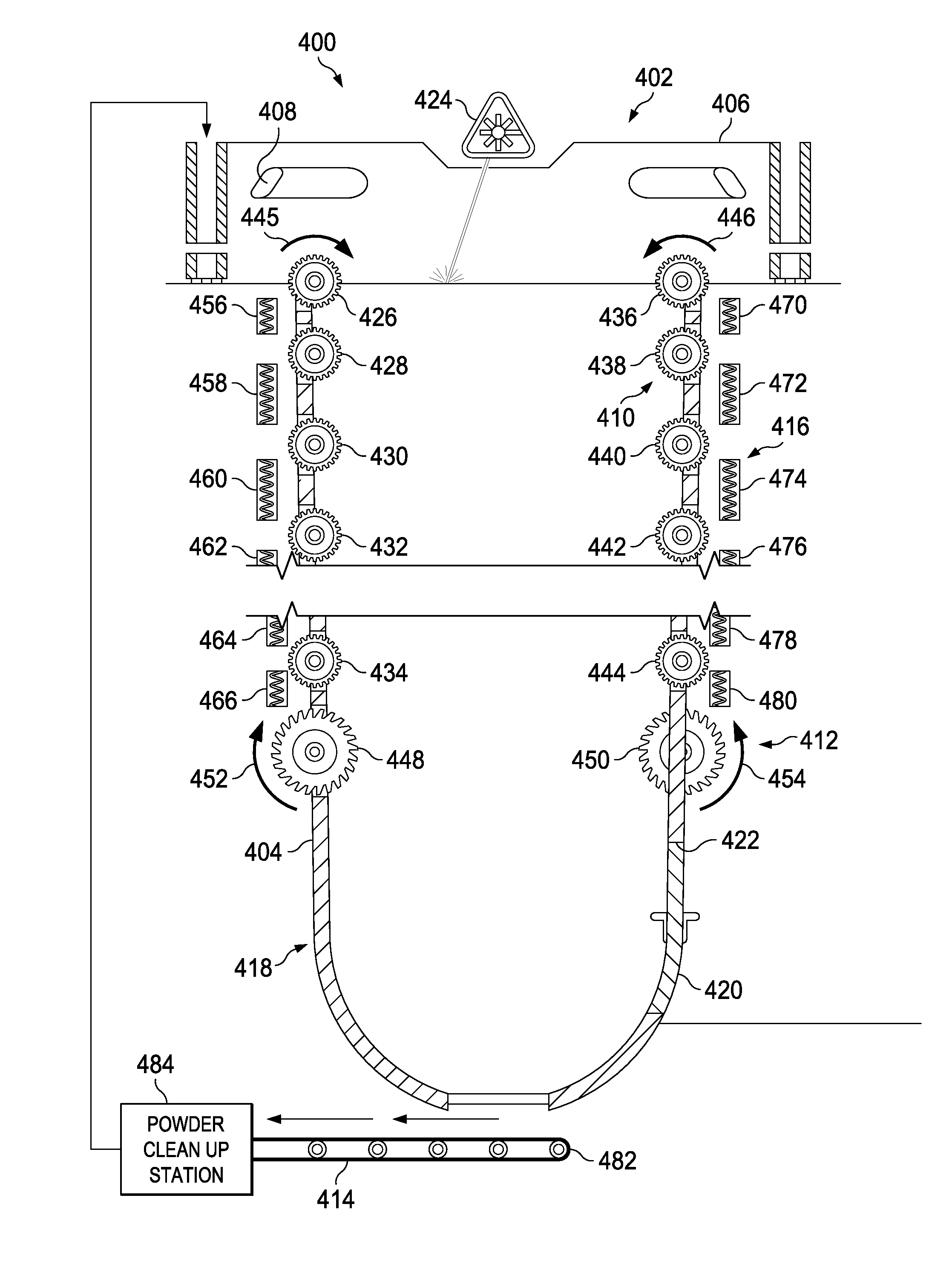
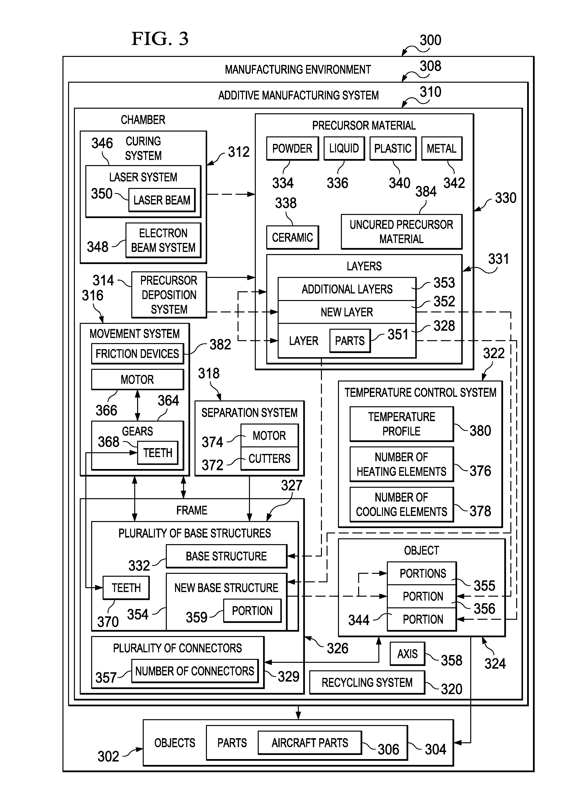
[0014]In a further advantageous embodiment, a laser sintering apparatus may comprise a chamber, a curing system, a movement system, a precursor deposition system, a temperature control system, a separation system, and a recycling system. The curing system may be configured to cure portions of layers of precursor material deposited in the chamber to form an aircraft part and a frame connected to the aircraft part. The frame may comprise a plurality of base structures and a plurality of connectors and may be configured to support the aircraft part during formation of the aircraft part in the chamber. The curing system may be selected from at least one of a heating system, a laser, and an electron beam. The movement system may be configured to engage the frame and move the frame connected to the aircraft part as a new layer of precursor material may be placed on a prior layer of precursor material. The movement system may comprise a plurality of gears having first teeth configured to engage second teeth formed on sides of the plurality of base structures. The precursor deposition system may be configured to deposit the new ...

Problems solved by technology

Although additive manufacturing may provide for rapid production of parts, this type of manufacturing may not be suitable for all types of parts.
Additionally, additive manufacturing may be limited by the cost of systems used to make parts.
Further, additive manufacturing may also be limited in terms of the types of parts made based on ...

Method used


Image

  • Continuous Linear Production in a Selective Laser Sintering System
  • Continuous Linear Production in a Selective Laser Sintering System
  • Continuous Linear Production in a Selective Laser Sintering System

Examples


Embodiment Construction

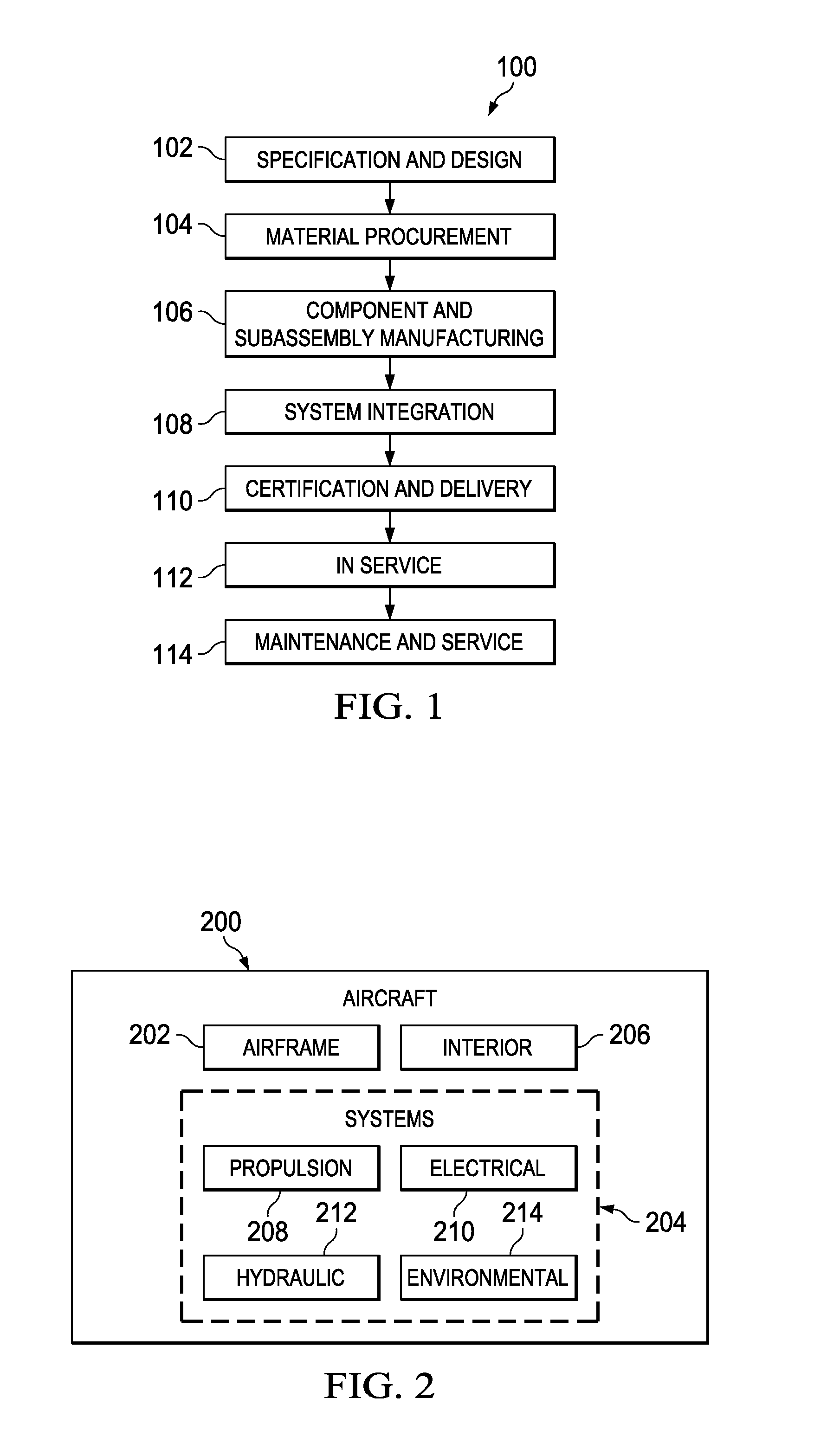
[0028]Referring more particularly to the drawings, embodiments of the disclosure may be described in the context of aircraft manufacturing and service method 100 as shown in FIG. 1 and aircraft 200 as shown in FIG. 2. Turning first to FIG. 1, an illustration of an aircraft manufacturing and service method is depicted in accordance with an advantageous embodiment. During pre-production, aircraft manufacturing and service method 100 may include specification and design 102 of aircraft 200 in FIG. 2 and material procurement 104.

[0029]During production, component and subassembly manufacturing 106 and system integration 108 of aircraft 200 in FIG. 2 takes place. Thereafter, aircraft 200 in FIG. 2 may go through certification and delivery 110 in order to be placed in service 112. While in service 112 by a customer, aircraft 200 in FIG. 2 may be scheduled for routine maintenance and service 114, which may include modification, reconfiguration, refurbishment, and other maintenance or servic...


PUM

PropertyMeasurementUnit
Temperatureaaaaaaaaaa
Flow rateaaaaaaaaaa
Structureaaaaaaaaaa

Abstract

A method and apparatus for forming objects. Layers of precursor material may be placed on top of each other. The layers of precursor material may be selectively cured as the layers of precursor material are placed on top of each other to form an object and a frame associated with the object.

Description

BACKGROUND INFORMATION[0001]1. Field:[0002]The present disclosure relates generally to manufacturing objects and, in particular, to a method and apparatus for manufacturing objects using additive manufacturing. Still more particularly, the present disclosure relates to a method and apparatus for manufacturing objects using selective laser sintering.[0003]2. Background:[0004]Manufacturing of objects may be performed in a number of different ways. For example, objects, such as aircraft parts, may be manufactured using additive manufacturing. Additive manufacturing may be a process of joining materials to make objects. These objects may be made by using models of the desired object.[0005]Additive manufacturing may be performed using various technologies. For example, without limitation, an aerosol jetting system may send a stream of particles towards a substrate. The particles on the substrate may be heated to a temperature to cause the particles to adhere to each other.[0006]As anothe...

Claims


Application Information

Patent Timeline
IPC IPC(8): B32B37/02B29C65/02B29C65/16B32B37/00B29C65/14
CPCB29C67/0092B33Y10/00B33Y30/00B22F10/00B22F10/73B22F12/33B22F12/20B22F10/28B22F12/10B22F10/322B22F12/50B22F12/224B33Y40/00B29C64/40B29C64/153B29C64/35B29C64/393B29C64/357Y02P10/25B33Y50/02B28B1/001B28B17/0081
Inventor LYONS, BRETT IAN
Owner THE BOEING CO
Why Eureka
Try Eureka