

Power supply arrangement for multi-stage amplifier
a multi-stage amplifier and power supply technology, applied in the direction of amplifiers, gated amplifiers, electrical devices, etc., can solve the problems of poor operating efficiency, tight time alignment limits, and difficulty in providing supply modulation on more than one amplifier stag
- Summary
- Abstract
- Description
- Claims
- Application Information
AI Technical Summary
Benefits of technology
Problems solved by technology
Method used
Image

Examples
second embodiment
[0102]With reference to FIG. 3, there is illustrated a second embodiment in accordance with an inventive arrangement. The multi-stage amplifier arrangement of FIG. 3 is generally denoted by reference numeral 300, and corresponds to that of FIG. 2 but the voltage selection stage 204 of FIG. 2 is replaced by a multi-supply stage 302. The multi-supply stage 302 is an exemplary implementation of the slow supply stage 102 of FIG. 1
[0103]The multi-supply stage 302 receives the voltage signal on line 230 from the battery 212, and in addition receives the control or selection signal on line 224 from the voltage selection control stage 202. The output of the multi-supply stage 302 is provided on line 304, and provides a supply voltage for the driver stage 106.
[0104]The arrangement of FIG. 3 differs to that of FIG. 2, insofar as the power supply stage for the driver stage is provided with its own multi-supply stage 302. Thus the voltage supply on line 304 provided by the multi-supply stage is...
third embodiment
[0105]a multi-supply stage arrangement in accordance with the inventive arrangement of FIG. 1 is illustrated with reference to FIG. 4, and denoted by reference numeral 400. The arrangement of FIG. 4 corresponds to that of FIG. 3, but the multi-supply stage 302 is adapted to receive a reference signal on line 410 which is derived from the output of the HAT 206. Thus the voltage selection control stage 202 of FIG. 3 is dispensed with, and a reference signal on line 410 is used to control the voltage of the multi-supply stage 302 to be provided as a supply voltage on line 304. The multi-supply stage can provide one of a set of fixed voltage levels as the supply voltage on line 304, or provide a continuously varying supply voltage.
[0106]A low pass filter (LPF) denoted by reference numeral 402 receives the modulated supply voltage on line 240 delivered to the power amplifier stage, and provides a filtered version of such on line 410 as the reference signal. The low pass filter 402 thus p...
fourth embodiment
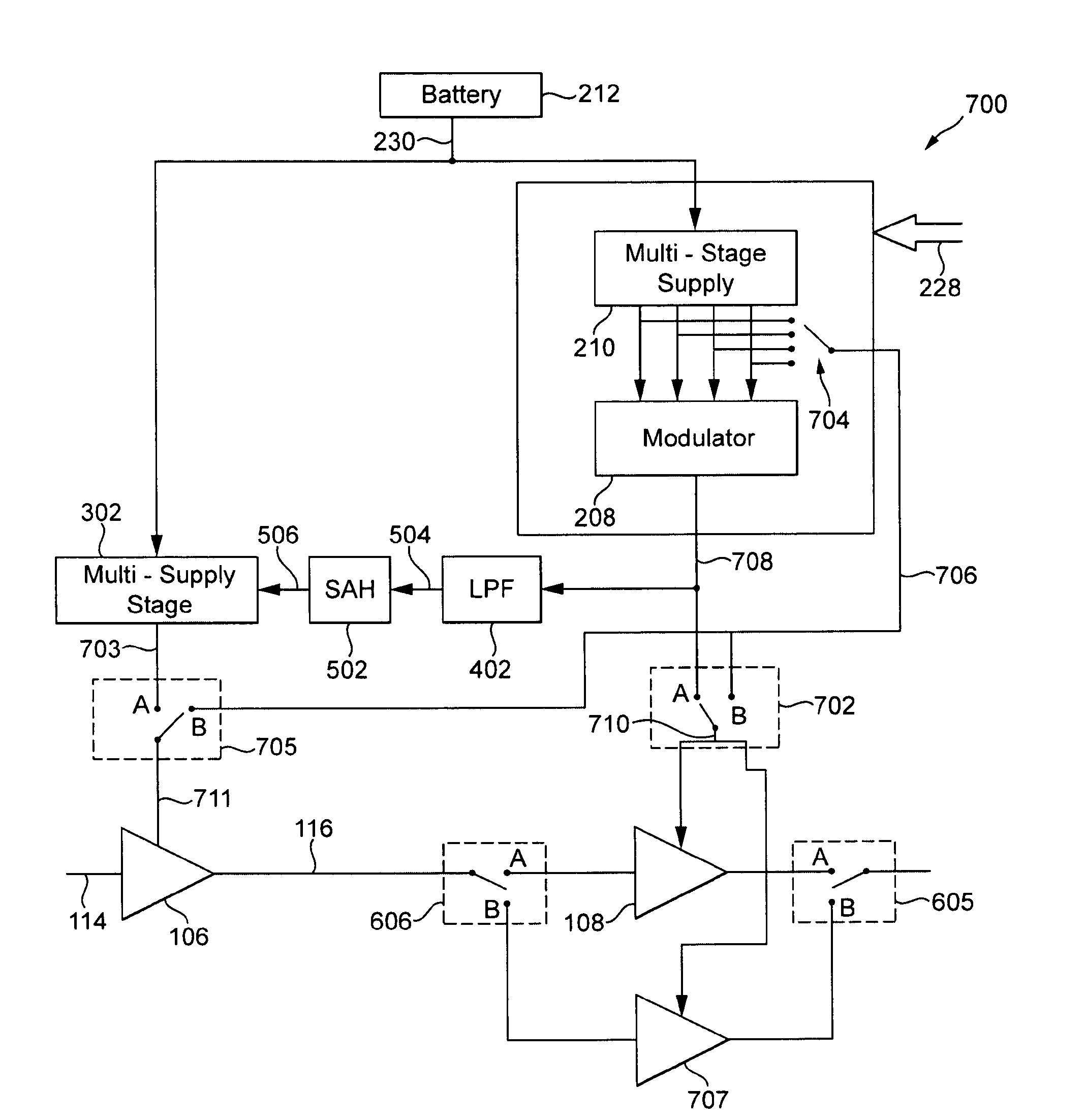
[0110]With reference to FIG. 5, there is further illustrated a fourth embodiment for implementing the multi-amplifier arrangement in accordance with the inventive arrangement of FIG. 1. In FIG. 5, the multi-stage amplifier arrangement is generally denoted by reference numeral 500.
[0111]The embodiment of FIG. 5 generally corresponds to that of FIG. 4, with the addition of a sample-and-hold (SAH) block between the low pass filter 402 and the multi-supply stage 302. The output of the low pass filter 402 on a line 504 forms an input to the SAH block 502, and in the output of the SAH block on line 506 forms the input to the multi-supply stage 302, being the reference signal for selection of the appropriate fixed supply voltage.
[0112]The sample-and-hold block ensures that the power supply stage for the driver amplifier is provided with a reference signal, on line 506, which remains constant across a given time slot or other given time period. The sample-and-hold block 502 may be triggered...
PUM
 Abstract
Description
Claims
Application Information