Bridgeless power factor correction converter

a power factor and converter technology, applied in power conversion systems, climate sustainability, energy industry, etc., can solve the problems of reducing the efficiency of power factor correction converters, surges in input current and input voltage, and loss of bridges,

Inactive Publication Date: 2012-03-22
TDK CORPARATION
View PDF1 Cites 44 Cited by
  • Summary
  • Abstract
  • Description
  • Claims
  • Application Information

AI Technical Summary

Problems solved by technology

However, it is known that, when a rectifying bridge is provided as described above, the loss in the bridge inhibits an increase in the efficiency of the power factor correction converter and its size reduction.
The above-described TPBL converter, however, has a problem in that an excessive surge current flows into the inductor at the zero cross point of the input voltage and accordingly a surge occurs in the input current and the input voltage.
The surge current and the surge voltage increase the noise of the converter, i.e., an electromagnetic interface (EMI) noise, which reduces the efficiency.

Method used


Image

  • Bridgeless power factor correction converter
  • Bridgeless power factor correction converter
  • Bridgeless power factor correction converter

Examples


first embodiment

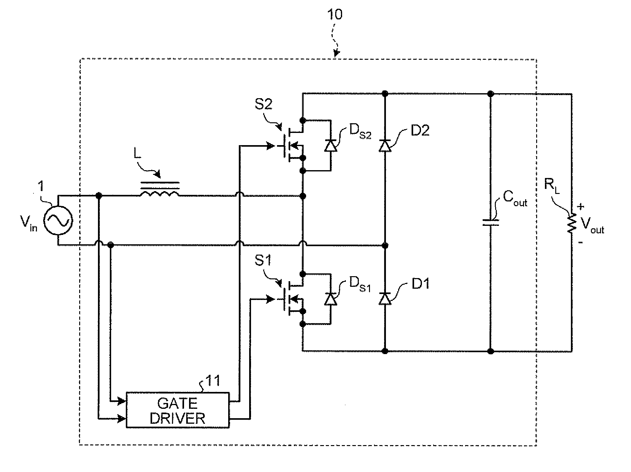
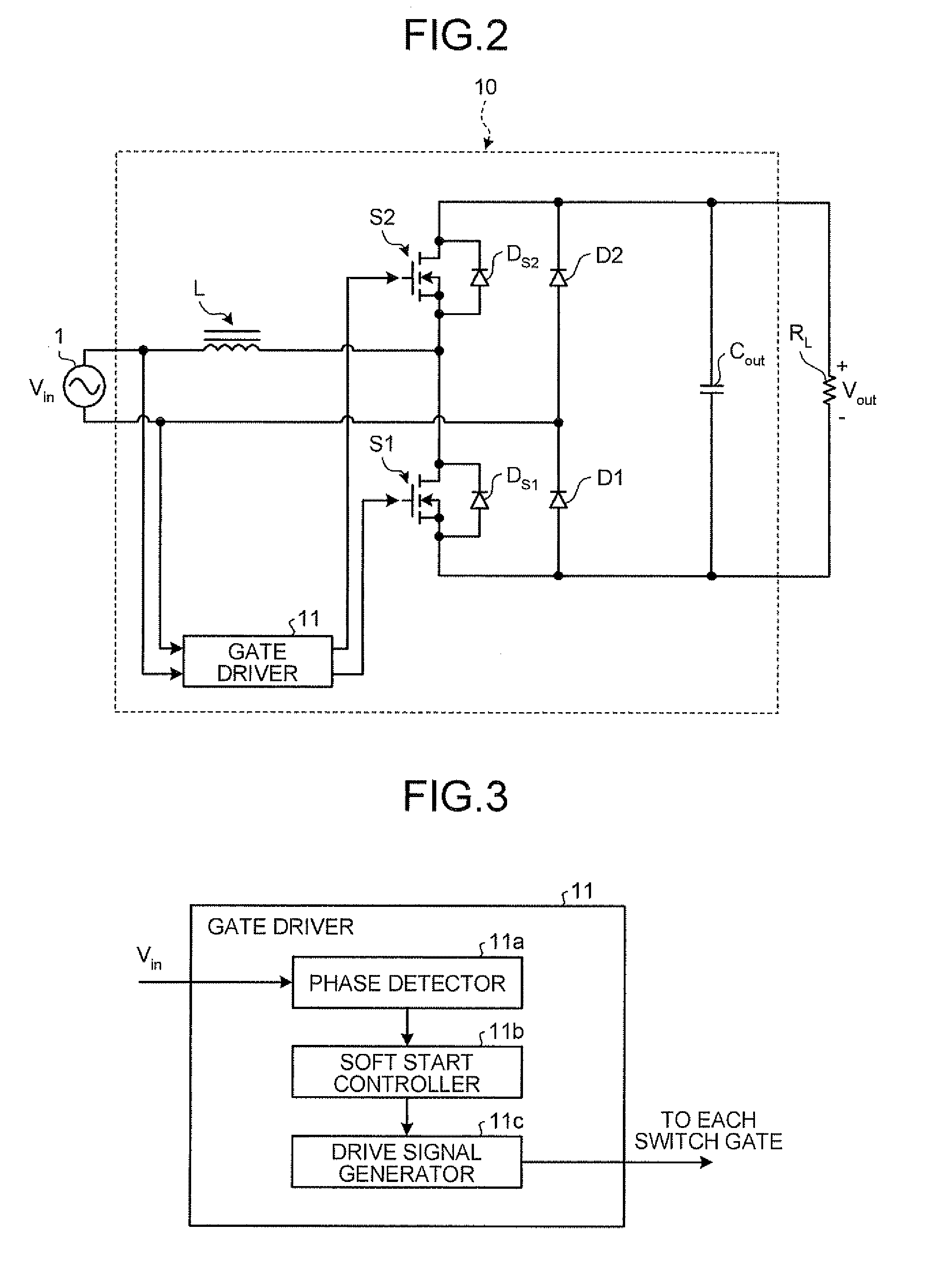
[0044]FIG. 2 is a diagram of a circuit configuration of a bridgeless power factor correction converter 10 according to the first embodiment. As shown in FIG. 2, the bridgeless power factor correction converter 10 boosts an input voltage Vin and produces a direct current (DC) output voltage Vout with a load resistance RL.

[0045]As shown in FIG. 2, the bridgeless power factor correction converter 10 includes the booster inductor L, the switching device S1, the switching device S2, the diode D1 and the diode D2, which are one-direction devices, the capacitor Cout, and a gate driver 11 that drives the gate of each switching device.

[0046]A normal booster converter is configured by connecting one terminal of a booster inductor to the positive side of an input power supply and connecting the other terminal of the booster inductor to the switching devices and the anode of an output diode. In the bridgeless power factor correction converter 10 shown in FIG. 2, every time the voltage polarity ...

second embodiment

[0112]FIG. 13 is a diagram of a circuit configuration of a bridgeless power factor correction converter according to the second embodiment. FIG. 13 shows a bridgeless power factor correction converter 20, known as an interleaved converter, including parallel two booster converters each consisting of the inductor L, the switching device S1, and the switching device S2.

[0113]The same components in FIG. 13 as those in FIG. 2 are denoted by the same reference numbers as those in FIG. 2. The redundant descriptions of the components denoted by the same reference numbers as those in FIG. 2 will be omitted below.

[0114]As shown in FIG. 13, the bridgeless power factor correction converter 20 includes a booster converter consisting of the inductor L1, the switching device S1, and the switching device S2; and a booster converter consisting of an inductor L2, a switching device 53, and a switching device S4. FIG. 13 shows a body diode DS3 of the switching device S3 and a body diode DS4 of the sw...


PUM


Abstract

A bridgeless power factor correction converter is configured such that a gate driver controls the ON ratio of a booster converter switch so that the ON ratio is gradually increased from 0, i.e., performs soft start control, every time the voltage polarity of an AC input in a totem-pole bridgeless power factor converter (TPBL converter is inverted) is inverted.

Description

CROSS-REFERENCE TO RELATED APPLICATIONS[0001]This application is based upon and claims the benefit of priority from Japanese Patent Application No. 2010-211203, filed on Sep. 21, 2010, the entire contents of which are incorporated herein by reference.BACKGROUND OF THE INVENTION[0002]1. Field of the Invention[0003]The present invention relates to a bridgeless power factor correction converter that has no bridge circuit to rectify an alternating current input.[0004]2. Description of the Related Art[0005]Conventionally, a switching power supply that is connected to an alternating current (AC) input uses a power factor correction converter in order to correct the power factor of the input current and inhibit the harmonic current. Normal power factor correction converters usually use a boost converter to control power factor correction after using a diode bridge to rectify an AC voltage to a positive DC voltage.[0006]However, it is known that, when a rectifying bridge is provided as desc...

Claims


Application Information

Patent Timeline
Patent Type & Authority Applications(United States)
IPC IPC(8): H02M7/06
CPCY02B70/126H02M1/4208Y02B70/10Y02P80/10H02M1/0085
Inventor TOMIOKA, SATOSHI
Owner TDK CORPARATION
Why Eureka
Try Eureka