Bridgeless power factor correction converter

A power factor correction and converter technology, applied in the direction of output power conversion device, high-efficiency power electronic conversion, irreversible AC power input conversion to DC power output, etc., can solve the impact current flow, efficiency drop, input current and input Problems such as voltage shock

Inactive Publication Date: 2012-04-11
TDK CORPARATION
View PDF4 Cites 28 Cited by
  • Summary
  • Abstract
  • Description
  • Claims
  • Application Information

AI Technical Summary

Problems solved by technology

[0005] However, the above-mentioned TPBL converter has a problem that an excessive surge current flows into the inductor at the zero-crossing point of the input voltage, so that a surge occurs in the input current and the input voltage
Inrush current and inrush voltage increase the noise of the converter, that is, electromagnetic interference (EMI) noise, thereby reducing efficiency

Method used


Image

  • Bridgeless power factor correction converter
  • Bridgeless power factor correction converter
  • Bridgeless power factor correction converter

Examples


no. 1 example

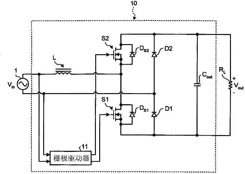
[0042] figure 2 is a diagram of the circuit configuration of the bridgeless power factor correction converter 10 according to the first embodiment. Such as figure 2 As shown, the bridgeless power factor correction converter 10 makes the input voltage V in boost, and utilizes a load resistor R LGenerates a direct current (DC) output voltage V out .

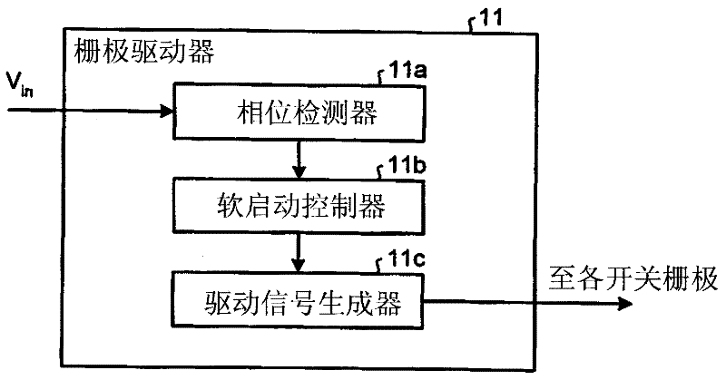
[0043] Such as figure 2 As shown, the bridgeless power factor correction converter 10 includes a boost inductor L, a switching device S1, a switching device S2, diodes D1 and D2 as unidirectional devices, a capacitor C out , and a gate driver 11 for driving the gate of each switching device.

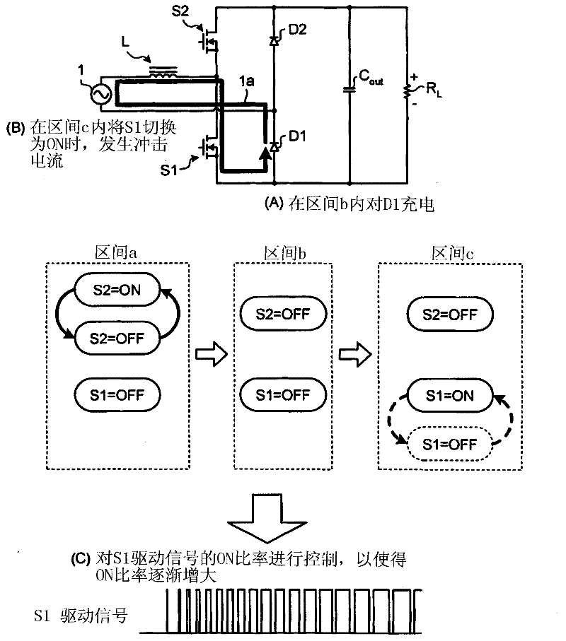
[0044] A typical boost converter is configured by connecting one end of a boost inductor to the positive side of an input power supply, and connecting the other end of the boost inductor to a switching device and the anode of an output diode. exist figure 2 In the bridgeless power factor correction converter 10 shown, whenever the...

no. 2 example

[0115] Figure 13 is a diagram of the circuit configuration of the bridgeless power factor correction converter according to the second embodiment. Figure 13 A bridgeless power factor correction converter 20 known as an interleaved converter is shown, wherein the bridgeless power factor correction converter 20 comprises two boost converters connected in parallel, each comprising an inductor L , Switching device S1 and switching device S2.

[0116] use with figure 2 The reference numerals with the same reference numerals are denoted by Figure 13 neutralize figure 2 components of the same components. The following will omit the pair by and figure 2 Redundant description of components denoted by the same reference numerals.

[0117] Such as Figure 13 As shown, the bridgeless power factor correction converter 20 includes a boost converter including an inductor L1 , switching devices S1 and S2 , and a boost converter including an inductor L2 , switching devices S3 and ...


PUM


Abstract

A bridgeless power factor correction converter is configured such that a gate driver controls the ON ratio of a booster converter switch so that the ON ratio is gradually increased from 0, i.e., performs soft start control, every time the voltage polarity of an AC input in a totem-pole bridgeless power factor converter (TPBL converter is inverted) is inverted.

Description

technical field [0001] The present invention relates to a bridgeless power factor correction converter without a bridge circuit for rectifying an AC input. Background technique [0002] Traditionally, switching power supplies connected to an alternating current (AC) input use power factor correction converters to correct the power factor of the input current and suppress harmonic currents. A general power factor correction converter usually uses a boost converter to control power factor correction after rectifying the AC voltage into a positive DC voltage using a diode bridge. [0003] However, it is known that when a rectifier bridge is provided as described above, loss of the bridge suppresses an increase in efficiency of a power factor correction converter and miniaturization thereof. Therefore, various bridgeless power factor correction converters that do not include a bridge have been proposed (see Japanese Patent Application Laid-Open No. 2007-527687). [0004] One b...

Claims


Application Information

Patent Timeline
Patent Type & Authority Applications(China)
IPC IPC(8): H02M1/42
CPCH02M1/4208Y02B70/126H02M7/12H02M1/42Y02B70/10Y02P80/10H02M1/0085
Inventor 富冈聪
Owner TDK CORPARATION
Why Eureka
Try Eureka